Plastic Mould Ejection
Injection moulding compounds exhibit a certain amount of shrinkage,i.e., in a cooled condition, the volume is somewhat smaller than in a heated condition.
If parts with accurate dimensions are needed, allowances must be made for this shrinkage when establishing the dimensions of the cavities.
Shrinkage also causes the molded parts to sit tight on the cores since usually parts are ejected after they have cooled down.
As a result, extraordinary measures are required to be able to eject finished parts.
These measures include, first of all, careful polishing of all mold surfaces that come in contact with the plastics melt as well as a certain draft in the direction of draw.
Since self-acting slight lubrication of the mold surfaces that come in contact with the molded parts is possible only in rare cases,there is a danger that scratches and cracks will occur when the mold is opened or the parts ejected, particularly if the molding compound is very hard.
A mirror finish, which is easily obtained by buffing a hard steel surface,is in no way adequate; it is far more important to grind and polish the areas in the direction of ejection with an oilstone to eliminate any scratches and indentations.
Wherever possible the surface should be polished, since even microscopic scratches and indentations are filled with plastics melt under the high injection pressure, thus preventing smooth ejection.
Proper surface finishing takes up a considerable portion of the total mold production time.
The function of an ejection system is to enable the removal of the moulded component from the mould once solidified.
Ejection mechanisms vary enormously, both in function and design. Choice of ejection method is usually dependent on some factors, for example:
- Design of component to be ejected;
- Aesthetic considerations of the component;
- Production requirements.
It will be evident that careful consideration must be given to the design and choice of ejection method when designing both components and moulds for injection moulding purposes.
considerations for ejection method
Before selecting an ejection method,sufficient thought must be given to the various component requirements. It may prove beneficial to construct a short list of requirements for the component to be moulded. Such a list should include references to the following:
(a) Component aesthetics.
(i) Can ejector pin marks be tolerated on visual presentation faces? Reversing the cavity within the mould design is not an uncommon practice to overcome this problem.
(ii) Does sufficient draft angle exist on the mould cavity walls to avoid component ‘scuffing’ or ‘dragging’ occurring during ejection? Adequate drafting of any moulded component is essential and should be considered as part of the component design before the designing of the mould.
(b) Component dimensional considerations.
(i) What amount of ejection induced distortion can be tolerated dimensionally? Moulded components can easily be distorted during ejection if unsupported and especially in the case of thin-walled mouldings.
(ii) Will additional ribs be required to enable ejection to take place without distortion resulting?
(c) Machine considerations.
(i) Is the ejection force sufficient to eject the component within the working limitations of the moulding machine? Mould designers will often design a whole mould without giving ejection force requirement a thought,resulting in disastrous consequences.
(ii) Is the intended moulding machine able to actuate the designed ejection system incorporated into the mould design? Machine designs may vary with respect to ejection actuation method. The majority of moulding machines ejection actuate on the centre line of the platens in line with the injection unit.
Whereas a minority of machines actuate by means of crosshead plungers or puller plates,very large machines tend to employ cross-headed assemblies to distribute the larger forces as evenly as possible.
(iii) Will additional “core pulling” or actuation circuits be required? With complicated mould designs,multicore pulling may be a design requirement. For this purpose the moulding machine should possess additional hydraulic core pulling circuits and the necessary means of actuation control.
(iv) With the moulding machine/mould combination fully open, will sufficient “daylight“(open space) exist to allow for component ejection and clearance? Failure to allow for sufficient daylight will mean that the mould will have to operate in a larger,more costly machine with a greater opening stroke. The running of a smaller mould in a large machine could lead to the following problems:
- -material degradation, caused by longer barrel residual times; higher levels of mould wear as a result of increased clamping pressures;
- -component Hashing, created by the ‘rocking’ of the platens on closure with the smaller projected area of the mould;
- -shot inconsistency due to the utilisation of a large volume injection unit delivering a small shot volume;
- -increased cycle times; larger machines tend to move more slowly than their smaller counterparts.
(v) Is the required ejection stroke within the capability of the moulding machine? Mouldings of greater draw depth,e.g. tubes will require long ejection strokes with which to eject them.
The maximum available ejection stroke on the moulding machine is determined by the length of the ejector cylinder (i.e. the swept volume of the piston on actuation). This has to be investigated by the mould designer if stroke length is in doubt.
(d) Plastic Mold/tooling considerations
(i) Is the ejection system to be employed for cavity vent purposes? Ejector pins, etc. are frequently added to a mould design to vent gas traps where blind spots occur within the cavity.
(ii) Will the ejection system be required to release interfacial vacuums between the component and the mould core prior to the component being ejected? Large thin-walled mouldings, such as lids, fully encase the core on mould opening and a vacuum is created underneath the component during ejection.
Thin-walled brittle mouldings are easily cracked or broken by the holding force of the vacuum if not released or vented in time.
(iii) Ejection components such as pins and blades induce high levels of wear to the mould core components during service.
Plastic Mold Ejection Methods
Pins and blades ejection
Ejector pins provide one of the cheapest forms of ejection available although their use has limitations, One such limitation is that due to the very small projected area of the pins, high single point loading is transferred to the moulding during the ejection cycle.
Component damage or distortion may result where pins are located, especially in the case of thin-walled mouldings or when brittle materials are used.
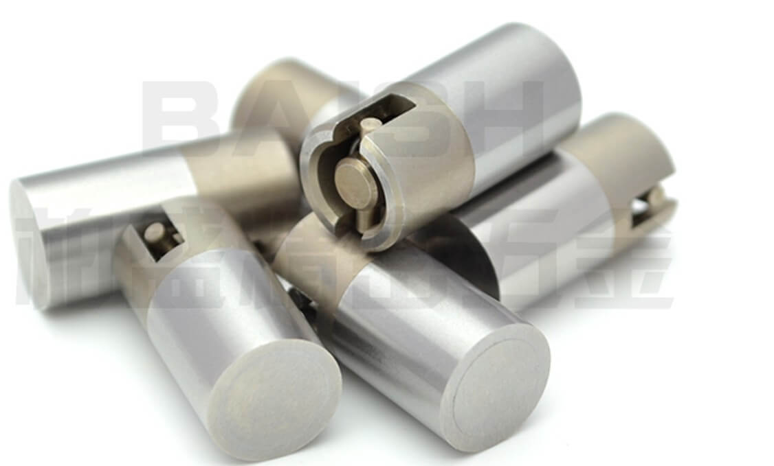
Ejector pins are usually fitted as standard mould components due to their cheapness and ease of availability from standard mould part suppliers. Pins are manufactured to standard formats in metric and imperial sizes.
Ejector sleeves
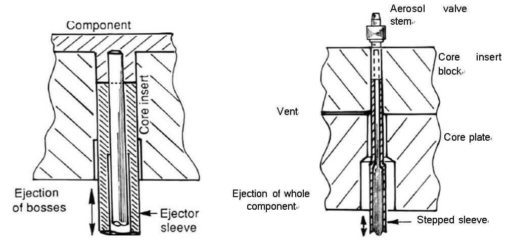
Ejector sleeves are employed to eject specific features such as bosses, recessed holes, etc.
Small round components can be ejected by the use of one ejector sleeve about their periphery. Ejector sleeves are more costly to employ than pins and tend to wear faster in use due to their having both internal and external working faces.
Ejection forces are more evenly distributed over the wider projected area offered by the sleeve in comparison to the standard ejector pin with the added benefit of effectively doubling the venting efficiency over the latter.

Valve ejectors
Valve ejectorsValve ejectors have many applications and can be employed for many different reasons. The various designs of valve ejector are usually concerned with the fixing or actuation method employed.
Valve ejectors offer large projected areas for load transmission. The flat head design ensures that adequate support can be provided to thin-walled components without undue distortion resulting on actuation.
Soft flexible polymers and components, e.g. HDPE bottle caps and closures, frequently employ this form of the ejector to form seal undercuts and aid ejection. Floating valve ejectors can be employed in vertically used injection moulds or compression moulds utilizing gravity to return them after actuation.
Stripper ring and plate ejection
Stripper rings and plates eject components by pushing or pulling them off the mould core,usually by means of total peripheral contact about the component base.
Stripping of components provides benefits in terms of good component support during the whole ejection phase resulting in less distortion or damage being inflicted.
The use of such ejection methods, although beneficial in many ways, can result in higher levels of tool wear occurring due to the increased size of the ring or plate bush locational features about the mould cores.
Air ejection

Combinations of the various mechanical ejection methods are often coupled with the use of air (pneumatic) ejection when the need arises.
Many examples of the use of air/mechanical ejection can be found in the thermoplastic and rubber industries for components such as gaskets, seals,diaphragms, etc. Large,thin-walled lightweight components often utilize air ejection techniques due to their large projected areas, which make conventional ejection difficult if the component damage is to be avoided.


my WhatsApp number 7458848121
please send all theory
design autocad,nx,cnc,plastics mold design.
Thank
you could find so many online.