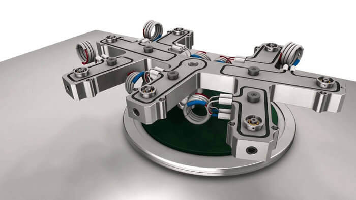
Among the major advantages of hot-runner molds is the material savings that result from eliminating the runner system. In essence, hot-runner systems are extensions of the plastic injection machine’s nozzle through which the plastic melt flows straight into the cavities.
Providing the weight of a part is the same, it is less expensive for it to be plasticized in a cold runner mold than it is for a hot runner mold. The machine’s recovery time, and thus its overall cycle time, is also reduced correspondingly, thereby increasing its overall productivity.
It is especially useful in molds that have many cavities, especially molds for small components and molds for quality components exposed to high loads that cannot be regrinded.Although most hot runner molds require a cold runner system, converting cold runner molds is a method of achieving the processing and economic benefits of hot runner molds.
On average, however, time and material can be saved in substantial amounts.
However, despite the above advantages, it cannot be denied that the general use of hot runner molds encounters certain difficulties as well as the necessity of extra temperature regulators and heating systems.
Heat balance considerations
The most commonly encountered problems with hot-runner molds ,regardless of the hot-runner system used occur because of inadequate heat balance. This shortcoming may be the result of very different causes.
For instance,problems with externally heated hot runner nozzles with wound heating elements may be the result of too little heat transfer surface,which leads to complete failure of the hot-runner system. Identical problems may occur when using cartridge heaters if a proper seat is not provided.
In this case,the insulating action of the resulting air gap between the cartridge heater and bore may lead to a heat buildup in the cartridge on the one hand and at least locally inadequate heating on the other even though the heating capacity has been properly determined.
The heat buildup in the cartridge is often the cause of premature failure,i.e., shortened service life.
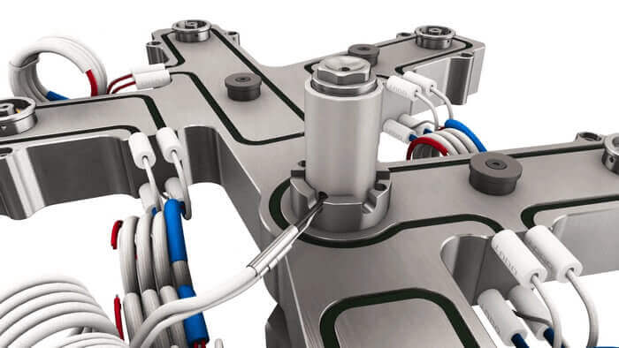
Tubular heating elements that have been embedded in thermally conducting cement in coarsely machined channels have proved quite successful.
Since these tubular heating elements can be individually adapted to local requirements in accordance with the layout of the hot-runner manifold, they can contribute to an improved heat balance in many cases. When proper procedures are followed, i.e.,
- Entrapped air in the thermally conducting cement is avoided
- All surfaces of the tubular heating element and channel are coated with the thermally conducting cement
- The instructions of the manufacturer with regard to curing of the thermally conducting cement are observed
tubular heating elements exhibit a long service life and little susceptibility to failure. Because of the brittleness and tendency of the thermally conducting cement to crumble,the channels must be covered. For thermal reasons , this is accomplished preferably with bright cold rolled or polished aluminum plates fastened to the hot-runner manifold.
The requirement for a uniform heat balance in the hot-runner manifold includes especially the requirement for as few local temperature differences as possible, as this is a necessary prerequisite for identical temperatures at the tips of the probes (torpedos) ,when these are heated indirectly by the hot-runner system.
To achieve as few temperature fluctuations in the hot runner manifold as possible
- The mass of the block should be as high as possible
- The heat losses should be as low as possible
- The temperature should be controllable.
In determining the heating capacity,specific values of 150 to 300 W/kg of hot-runner manifold have proved successful.
It should be noted that in particular too high a specific heating capacity (>300 W/kg of the hot-runner manifold) can lead to large,undesirable fluctuations of the hot-runner manifold temperature The use of quasi continuous controllers with reduced power output during startup is to be recommended for controlling the temperature of the hot runner manifold.
It must,however,be borne in mind that even with the most elaborate temperature control system problems of heat balance cannot be corrected if at the same time measures to minimize the heat losses are not taken.
For instance,temperature differences of up to 60 °C were measured as the consequence of convective heat losses resulting from a chimney effect in a four nozzle hot-runner mold.
Continuous production of parts to specifications was not possible in spite of an otherwise properly laid out hot-runner system.
The chimney effect was easily eliminated by covering the open sections of the mold. This measure led to a significant reduction in temperature differences.
The goal of a uniform temperature can be achieved relatively easily through very simple, physically meaningful measures based on the laws of heat transfer.
The temperature difference between the hot runner manifold and the mold plates may be up to 300 °C.
More or less heat may be lost by radiation depending on the type of surface. This is true especially for surfaces with temper colors or even more for slightly rusted steel surfaces.
To minimize these losses at little cost,it is recommended that bright drawn or polished aluminum plates be fastened to the surfaces of the hot-runner manifold.
The use of coverings for the mold plates enclosing the hot-runner manifold provides an additional but relatively slight improvement. the radiant heat transfer between two slightly rusted steel surfaces can be up to an order of magnitude greater than that between surfaces of aluminum and rusted steel.
Further heat losses occur as the result of conduction in the support pads and locating bushings.
Since these losses are proportional to the areas of contact, these should be kept as small as possible while observing a maximum permissible force per unit area of about 300 N/mm2 for the supporting components.
These relatively high surface forces necessitate the use of hardened steel support components,as such high mechanical loads would otherwise lead to plastic deformation of the heated probes (torpedos). Designs in which locating bushes have not been used for reasons of simplicity have no proved successful.
The fits for the probe shank,locating bushing and locating bushing seat in the hot-runner manifold should always be a combination of H7/m6.
Electrical discharge machining has not proved useful because of the relatively rough surfaces that result and the danger of melt penetrating into the seat.
An insulating layer of 10 um,for instance,already leads to a reduction in heat transfer by about 10 %.
Control of the hot-runner manifold temperature can be accomplished quite simply. In many cases,a thermocouple and temperature controller suffice.
By consistently following laws of heat transfer,temperature fluctuations of only a few degrees may be achieved at the probe tips, thereby fulfilling an essential prerequisite for production of precision molded parts.
Closed loop control should always be preferred over open loop control, keeping in mind,however, that an attempt should be made to achieve maximum reliability with as little expense as possible.
Experience permits the general conclusion to be drawn that the most commonly encountered cause of greater or fewer problems and mistakes with hot-runner molds can be traced to poor attention to heat losses.
Heat losses always lead to impermissibly large temperature differences in the hot-runner manifold. The results are fluctuating part quality with respect to tolerances and properties and/or solidification of the melt during the molding cycle,that is, failure of the system.
The expense to minimize heat losses is generally low and is always justified as well as necessary for the reasons mentioned, since even a process controlled injection molding machine cannot correct for the effects of temperature differences or impermissibly high temperature fluctuations in the mold.
Multiple fits (double fits)
The hot-runner manifold is generally located in the mold and connected to the mold plate by means of •support pads and locating bushings.
In order to prevent impermissibly large amounts of deformation and at the same time reliably prevent leakage,certain tolerances as to the shape and location of the sealing surfaces with respect to one another are required.
This is achieved without the need for a great deal of machining by having the pressure pads.
For instance,in contact with only one common plane. This is accomplished by grinding the support pads to a common height with the aid of a surface grinder. Occasionally, two or more planes are provided for reasons of locating and positioning the hot-runner manifold,but these have not proved useful in practice because of the differing percentages of contact area resulting from the double or multiple fits, not to mention the increased amount of machining necessary.
Differing percentages of contact area (= different surface pressures) are often the cause of leakage in multiple cavity molds,especially in the region of sealing surfaces,e.g., between the probe locating bushing and the gate insert.
Melt can be forced into the air gap between the hot-runner manifold and mold plates and completely fill it.
As a result of the higher thermal conductivity of the plastics resin compared with that of air,this leads to a drastic distortion of the heat balance, since heat losses increased considerably.
Compensating for these heat losses by raising the hot-runner manifold temperature generally causes thermal degradation of the plastics melt,because the permissible processing temperature range is exceeded.
In addition to the thermal degradation and unpleasant odors, lower toxic limits may also be exceeded, which is impermissible for obvious reasons.
The pressure pads and locating bushings should be fitted with an overal interference of 0.05 mm. The resulting surface pressure should not exceed about 300 N/mm2.
By also taking the thermal expansion into account,reliable sealing is ensured so long as multiple fits are avoided.
End plugs
Inadequate attention to the design and fitting of an apparently incidental component such as the end plug in the hot runner is often the cause of leakage or problems when changing colors. The end plugs in hot runners must meet the following requirements. They must:
- Be absolutely leakproof
- Have no “dead corners
- Be secured against rotation
- Be removable
