Thin wall container mold
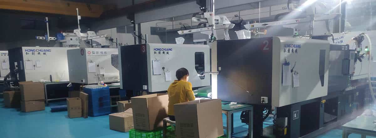
What if you could take the guesswork out of container production, from thin wall mould design to manufacturability? With Thin Wall Containers mould, we give you everything you need to create a perfect container without having to invest in new equipment and without the frustration of trial and error.
We offer both standard and custom thin wall mould, along with variety shapes, sizes, and materials; so it’s easy to find the right container for your exact needs.
Our company is producing a series of thin-wall moulds based on experience and knowledge. These moulds include
- spoon, fork and knife mould,
- thin-walled container mould,
- fast food box mould,
- thin wall bowl mould and
- other disposable thin wall moulds.
Nowadays, plastic containers are widely used in various applications, including food storage, snacks, oil packaging, and so on, from small to large, and can be found from 100 milliliters to 20 liters in size.
How to run thin wall injection molding
According to industry standards, thin wall parts using engineering resins have a wall thickness between 0.5mm and 1mm and a volumetric flow length to wall thickness ratio exceeding 75.
Amorphous resins, such as polycarbonate, challenge this definition, especially when used as engineering composites. Because a thinner wall section dissipates heat rapidly during injection, it changes processing, tool design, and part design rules. For this reason, the fill pressure will be up to 15,000-35,000 psi (100-240 MPa) and the fill time will be up to 0.75 seconds.
As a result of high fill pressures applied for short periods, mold equipment has to be capable of
- Pumps of high torque and accumulators are required for injection and clamping. The clamp force can be 4-6 tons/inch2 under fill pressures of 30,000 psi (200 MPa).
- High-precision sensors used to control hydraulic systems.
- Powerful machines whose platens are thick enough to prevent deflections to as little as 0.0005″ (0.013mm).
- The shot capacity can be limited to 40-70% by using a smaller barrel.
Tooling is affected by high pressure in the following ways
- The number of support pillars and the thickness of the plate(s) must be increased to prevent tool deflection.
- There needs to be more research on cavity-core shifting. The core may need to be interlocked to prevent shifting.
- Ventilation needs to be increased. Vaccum vents may facilitate faster fill speeds.
- In addition to numerous large gates, a melt-feed system that provides a high flow rate promotes easier filling.
- A hotrunner system is almost essential.
- Hardened tool steel of the highest quality must be used.
- To facilitate part ejection, ejector pins should have a large and numerous diameter (2x normal). Part ejection will be improved with low friction coatings.
- It is important that the entire tool has an equal thermal expansion.
Steel For Thin Wall Mold
For thin-walled moulds, The steel material should also be considered carefully.
We recommend at least 718 steel for thin wall mould making about 800 thousand.
If a mirror finish is required, H-13(DIN 1.2344) steel will be recommended.
The plastic mould life will be 1-3 million, and the product’s surface will also keep the same finish.
P20 steel is widely used for normal mould making, but the mold must be made very strong because of the higher pressure of thin-walled injection moulding.
H-13(DIN 1.2344) and other hard steels add an extra safety factor to thin wall moulds.
However, the H13 thin wall mould cost may be higher than that of the standard mould by 30%-40%.
The increased cost is usually offset by increased production performance.
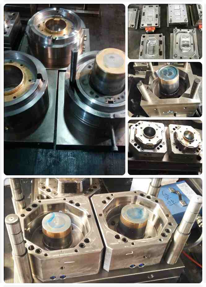
On the other hand, we will install a beryllium copper insert at the top of the core, with a depth of about 40mm, which can ensure better cooling to shorten the cycle time and allow customers to produce more products as quickly as possible.
In terms of the cooling system, we have our own ideas.
The diameter of the cooling channel and waterway layouts could assure the thin wall mould has the best cooling effect. Therefore, the thin-wall mould we made is of good quality, short cycle time, and fast delivery time.
If you want to make high-quality thin-walled moulds, look for China’s mould suppliers, Topworks plastic mold company will be your best choice.
You can get not only the quality thin-wall mould but also to get the best service.
Why thin wall mold get popular recently
One of the determining factors for the success of thin-walled injection molding is its speed.
By applying high pressure and fast filling into the mould cavity, molten thermoplastic can be injected into the cavity at high speed, preventing the gate from cooling and solidifying.
A complete injection moulding cycle can be completed in two seconds if the wall thickness can be reduced by 25%. This allows the filling time to be reduced by 50% within one second, thereby reducing the cycle time by one second.
With a thin-walled injection, there is less material to be cooled because the wall thickness is reduced.
The moulding cycle can be drastically reduced as the wall thickness decreases.
In a reasonable setting, neither the hot runner nor the runner system will interfere with the shortening of the moulding cycle.
Molding cycles are shortened to a minimum with the use of hot runners.
A Guide to Success in Thin-Wall Molding
It is one of the most coveted capabilities for an injection molder due to the need for smaller, lighter parts. Currently, thin-wall refers to components with walls less than 1 mm thick. Large automotive parts may be considered thin if their walls are 2 mm thick. Regardless of the circumstances, thinner wall sections require a different processing approach: higher pressures and speeds, faster cooling times, and a change in the gate and ejection system. As a result, mold, machinery, and part design have all been affected by these process changes.
| STANDARD VS. THIN-WALL PROCESSING | |||
|---|---|---|---|
| Key Factors | Conventional | Thin-Wall | |
| Typical Wall, mm. | 2-3 | 1.2-2 | <1.2 |
| Machinery | Standard | High-end | Custom |
| Inject. Pressure, psi | 9000-14,000 | 16,000-20,000 | 20,000-35,000 |
| Hydraulic System | Standard | Standard | Accumulators on injection & clamp units. Servo valves. |
| Control System | Standard | Closed-loop on injection speed, hold pressure, decompression speed, screw rpm, backpressure, and all temperatures. | Same as at left, with resolution of 0.40 in. on speed, 14.5 psi on pressure, 0.004 in. on position, 0.01 sec on time, 1 rpm on rotation, 0.10 ton on clamp force, 2° F on temperature. |
| Processing | |||
| Fill Time, sec | >2 | 1-2 | 0.1-1 |
| Cycle Time, sec | 40-60 | 20-40 | 60-20 |
| Tooling | Standard | Better venting, heavier construction, more ejector pins, better polish | Extreme venting, very heavy construction, mold interlocks, precise surface preparation, extensive ejection features, mold costs 30-40% higher than standard. |
Factors Related To Machinery
Many thin-walled applications can be handled by standard molding machinery. These machines offer a much broader range of capabilities than those available a decade ago. A standard machine can fill thinner parts due to improvements in materials, gating technology, and design.
A more specialized press able to handle higher pressures and speeds may become necessary as wall thicknesses decrease. Fill times of under 0.5 seconds and pressures exceeding 30,000 psi are common for portable electronics parts less than 1 mm thick. Injection and clamping cycles are often driven by accumulators in thin-wall molding machines. In addition to all-electric models, hybrid hydraulic/electric models are also becoming more common.
When clamping under high pressure, clamp force should be at least 5-7 tons per square inch. of projected area. As the thickness of the walls drops and injection pressures rise, extra-heavy platens aid in reducing flexure. There is generally a 2:1 or lower ratio between tiebar distance and platen thickness on thin-wall machines. Closed-loop control of injection speed, transfer pressure, and other process variables can also be effective in controlling packing and filling at high speeds and pressures with thinner walls.
Large barrels tend to have too much shot capacity. The shot size should be between 40% and 70% of the barrel capacity. If the parts are thoroughly tested for possible property loss due to possible material degradation, it may be possible to reduce the minimum shot size to 20-30% of barrel capacity in thin-wall applications. The user must be careful, as smaller shot sizes can result in longer barrel residence times for the material, thereby deteriorating its properties.
Make Your Molds Tough!
Fast molding is a key factor to success. To ensure that molten thermoplastic does not freeze in thinner cavities at a sufficient rate, faster filling and higher pressures are required. A reduction in thickness of 25% could reduce the time it takes to fill a standard part from 2 seconds to just 1 second if the thickness is reduced by 25%.
As the wall sections drop, thin-wall moldings have the benefit of requiring less cooling material. A reduction in wall thickness can save 50% in cycle times. Melt-delivery management can prevent runners and sprues from decreasing cycle-time advantages. A thin-wall molding operation often uses runner and sprue bushings that are heated to minimize cycle time.
It is also important to consider the mold material. In conventional applications, P20 steel is commonly used, but molds for thin-wall molding need to be built to withstand the higher pressures. A thin-wall tool made of H-13 or another tough steel is more safe. Injecting molten plastic at high speeds into the cavity will accelerate mold wear if you choose a material that won’t do this.)
Despite this, robust tools cost more than standard molds, perhaps even 30% to 40% more. However, increased productivity often compensates for the cost. It is often used to reduce tooling costs using the thin-wall approach. Increasing productivity by 100% can reduce the need for molds, saving money in the long run.
The following tips can help you design thin wall tools:
- Use steel that is harder than P20 when dealing with aggressive thin-walled applications, especially when you anticipate high wear and erosion. Gate inserts made from H-13 steel and D-2 steel are very effective.
- An interlocking mold may be able to prevent flexing and misalignment.
- Telescoped cores can reduce the risk of core shifting and breaking.
- Put thicker support plates (often 2 to 3 inches thick) along with preloaded pillars (typically 0.005 inches) under the cavities and sprues.
- Reduce pin pushing by using larger and more ejector pins than conventional molds.
- Place sleeves and blades strategically.
- When rings and ribs are polished with diamond no. 2, sticking problems are eliminated. Mold release can also be improved with nickel-PTFE surface treatments.
- In addition to venting along the parting line around 30% of the parting line, vented core pins and ejector pins are also available for facilitating ventilation. Vents typically measure between 0.0008 and 0.0012 in. in depth and 0.200 to 0.0400 in. wide.
- The parting line may not normally need to be sealed with an O-ring, however, some processors do so to break a vacuum inside the cavity for gas evacuation.
- As injection speed increases, gates larger than the nominal walls decrease material shear and gate wear, maintaining good packing by preventing freeze-off before it occurs.
- A Rockwell (Rc) hardness of 55 or more is usually necessary for high injection pressure gates.
- In order to reduce stress at the gate, aid filling and prevent part damage when degating, use gate wells when gating directly onto a thin wall with a sprue, pinpoint, or hot-drop.
- It is possible to reduce pressure loss in runner systems by using hot manifolds, but they need at least 0.5-in. diameters. They should have smooth inner passages without dead zones. There should not be heaters inside the manifolds. Using valve gates, if necessary, must be non-restrictive and strong enough to handle high pressures.
Additionally, thin-wall applications involve more critical cooling issues. Consider the following:
- Mold surface temperatures should be as uniform as possible by placing non-looping cooling lines directly in the core and cavity blocks.
- To keep steel at a desired temperature, rather than decreasing coolant temperature, increase coolant flow through the tool. It is recommended that the cooling fluid temperature difference between delivery and return do not exceed 6° or 10° F.