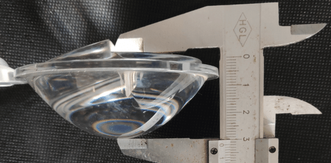
Polycarbonate injection molded lens design
Poly-carbonate injection molded optics should be designed according to a set of guidelines to minimize quality issues caused by unpredictability. In the following sections, you will find design guidelines for PC injection molding of optical lenses, but they can also be used for other plastic optical components. Since the purpose of a lens is to transmit light, understanding how light rays travel through the lens is an important first step in designing PC lenses. Based on the given refractive index of the material, a lens with curved surfaces on both sides of the lens will bend light rays based on the surface curvature of the lenses. It is important to consider several aspects of plastic PC lens design in this article.
-
Design principles:
Rays of light travel through plastic material in a straight line, which is how light is typically described as a wave. As a result of Snell’s law, light reflected within a plastic material bends at an angle of refraction after it enters. Light rays are bent so that they create a shadow on the same side of the focal point from an object on the other side of the plastic lens as the one from which they are coming. This is because plastic lenses have two spherical surfaces on which light rays bend. Therefore, in the design of a single lens, the geometric dimensions of the two surfaces and the lens thickness are generated so that the desired optical performance can be produced.
-
Surfaces:
It is believed that primary aberrations result from light waves that pass far away from the center of the lens in geometric optics. Using aspheric surfaces on lenses is a way of compensating for primary aberrations in the lens systems. SPDT allows for the machining of an aspheric surface quite readily since the mold surface is made by an insert so that it can be machined through the process quite easily. In modern smartphones, aspheric lenses play a large role in reducing the number of lenses within the camera, thus bringing down its size.
-
Tolerances:
An individual lens’ geometric dimensions are derived with the assumption that the geometric parameters of a given lens system have allowed variations in the geometric parameters of the lens. In order to produce optical lenses with the appropriate level of tolerance, design engineers design the molds, and then they determine the relevant process conditions so that the mold can be manufactured.
-
Thermo-coating:
As a result of temperature changes, Polycarbonate materials tend to change their refractive index more rapidly than glass because they have a greater coefficient of thermal expansion. To be able to account for temperature variations within a space, the CTE(coefficient of thermal expansion) must be considered when selecting a plastic material. Because plastic lenses cannot change their refractive index over time, they are inherently coated. Therefore, the surfaces of the lenses maximize light transmission. The final lens dimensions and coatings must be considered during the lens design process.
-
Dimensions
PC lenses usually have flat surfaces that are symmetrical along the axis. Thus, single-point diamond turning (SPDT) is widely used to machine optical surfaces and is one of the most common fabrication processes for plastic lenses. Due to this fact, the lens shape has been designed with associated mounting mechanisms and mounting mechanisms for the associated mounting mechanism. When plastic injection-molded lenses are compared to glass lenses, you see that they’re completely different in shape and thickness.
As well as the above points, some empirical aspects of lens design need to be considered. The first rule for lens geometry is to avoid any form of undercut, as it may lead to difficult demolding problems. Consequently, one should not demold the prototype using an angle greater than one degree. For air entrapment to be prevented in the lens during this phase, the thickness of the lens should be uniform as much as possible during the filling process.
For a more desirable filling pattern, smooth transitions should be allowed between different lens thicknesses. There are some lenses that require mounting parts with flanges or edges in order to attach to them. As a result, it is recommended that the gate is installed at the side of the lens cavity with an obvious geometrical orientation so that the lens can be installed correctly.


