It is possible to produce anything from simple to extremely complex plastic parts using injection molding, and it is possible to produce hundreds or millions of virtually identical plastic parts using injection molding.
It is not easy to construct and maintain injection mold tools, and making changes is difficult.
Tips to Maximize Injection Molded Parts
- Consistency is the best policy. The best flow will be achieved by maintaining the same wall thickness throughout your part. Ideally, walls should be 2-3mm thick. Conventional injection molding processes recommend a minimum of 1mm and a maximum of 4mm.
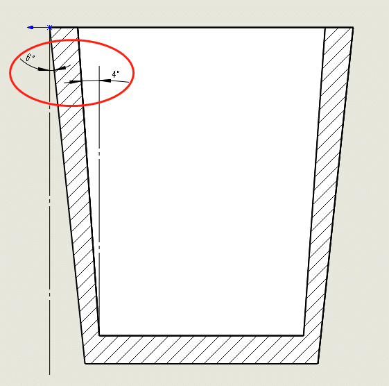
Smooth is the best option. When possible, use radii within the wall sections rather than abrupt transition points. - Draft. Draft angles can be helpful in releasing a part from a tool, but they can also pose design challenges, especially among parts that match. For untextured cores, a minimum draft angle of one degree is recommended; for textured surfaces, a minimum draft angle of three degrees should be recommended. Unless necessary, stay away from surfaces with no draft. You should strive to minimize the zero-draft surface area to a portion of the face rather than the whole surface to ensure proper part mating and tolerances.

- undercuts. Undercutting must be avoided. Lifters and slides are often used to create undercut features when simple will not suffice. For lifters and slides, at least two to three times as much clearance should be kept.
- Transition. When the plastic flows from the gate(s) inward, it will form a better part. The plastic should flow from the gate inward (where it flows to fill the parts).
- Sink (regional depressions caused by thicker plastic cooling at a slower rate) is problematic. It is important to follow some recommended guidelines if you want to reduce or eliminate the appearance of blemishes on cosmetic surfaces: On important cosmetic surfaces, avoid gates, ribs etc.;
A rib height should not exceed 3 times the wall thickness;
The wall thickness should not exceed 60% of the rib base.

- Datums. Establish part interfaces and interactions with the overall system using datums (features that serve as reference points). Assembly function is guaranteed when the product is created with a datum structure that matches the intended function.
- Interrogation. The Design for Manufacturing (DFM) reports provide valuable insight into why a specific design was chosen, including information like the location of ejector pins, gate locations, and parting lines (which are important during interactions with mating parts). Interrogate the design with inspection reports.
- Prototype. Current prototyping techniques, such as 3D printing, make it possible to test design concepts on individual components or even a whole part before investing in expensive tooling.