Details of the Operation Cycle
The details of a cycle for a “typical” horizontal, fully automatic, hydraulic clamp, reciprocating screw machine will now be described.
For illustration, assume an engineering thermoplastic, such as General Electric Noryl SE100, using a multi-cavity mold and a 200-tonne machine.
Noryl SE100 is a synergistic blend of two amorphous polymers— polystyrene (PS) and polyphenylene ether (PPE). Some of its outstanding properties are an HDTUL of 100 °C at 1.82 MPa, water absorption of only 0.07% in 24 hr immersion, and good electrical and strength properties.
Underwriters Lab (UL) continuous use rating is 80 °C for Noryl SE100 and up to 110 °C for some other blends in the Noryl family. In truckload quantities, the listed price (1991) is $2.32/lb or 0.560/cm3. Some of the setup and start information will be given later in the text.
Assume that the machine has been turned on, all parts are at proper operating temperature, and the material has been dried and fed into the machine at a steady rate.
The setup has been completed. All operating settings have been determined during startup, and the first parts are to be made. All safety gates and lockouts have been checked and are closed.
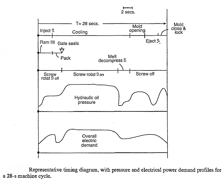
The machine is set for automatic operation, and the mold is empty, awaiting the first cycle. The figure below is a timing diagram for a typical cycle.
- Oil pressure closes the injection mold, using a fast closing speed with a small diameter cylinder, followed by high clamping pressure with the coaxial, larger diameter ram after the mold platens have come gently together.
The fast close motion is at a rate of about 76 cm/s, so a maximum stroke of 38 cm takes 0.5 s.
The two-stage motion protects the mold and the machine against closing down hard against a foreign object that may inadvertently hang on the parting surface.
Slow closing speed near the contact point also may be needed to protect mechanical side-core mechanisms in the mold.
The clamping force must be somewhat greater than the maximum force due to the pressure of the injected plastic.
If it is insufficient, the mold will open slightly, the melt will flash in excess, and part dimensions will be out of tolerance.
- As the screw turns (40-80 rpm), solid plastic is conveyed forward, melted, and pressurized. Barrel heaters are adjusted to bring melt temperature to within a band of ± 5 °C,and within the melting range of 250 °C—280 °G for Noryl SE100.
As in extrusion, the major portion of the heat input to the plastic is from viscous shear, not from the external barrel heaters.
The major difference between a simple extruder and the extruder section of the injection molder is that the reciprocating screw is not fixed axially—it can move forward and backward within its barrel.
As plastic melts, it is conveyed in front of the screw tip where it encounters sufficient resistance in the cold nozzle so that it accumulates, building up pressure that forces the screw to move backward.
The screw is supported at its rear by a thrust bearing, but the bearing housing is mounted on two hydraulic injection cylinders.
The injection cylinder backpressure is adjustable, usually set at 0.3-0.7 MPa for Noryl.
This backpressure is reflected directly in the condition of the melt accumulating in front of the screw.
Higher back pressure tends to improve additive dispersion and temperature homogeneity, but excess back pressure may cause material degradation, nozzle leakage, and wasted energy.
If backpressure is inadequate, then initial and final temperatures during injection will tend to be lower than in the middle of the stroke. The part may have non-uniform properties.
- When the screw moves back, it continues to rotate until it energizes an adjustable position limit switch that stops rotation and axial movement. Screw design must account for the rearward motion and still keep a sufficient part of the constant depth screw feed section under the throat of the hopper.
For a 200-tonne/410-cm3/50.8-mm diameter screw, this will require up to four extra flights in the feed section to allow for a 200- mm retraction of the screw. A 50.8-mm diameter screw can plasticize 37 g/s at a rate of 50% of the maximum.
For a maximum shot of 405 g, this means that the time to accumulate a full shot is 405/37 or about 11 s.
Screw rotation may be automatically slowed near the end of the refill stage to prevent overshooting shot size.
- The machine can be set with a timer to retract (suck back) the screw slightly at this point (for 1 or 2 s before injection and about 2.5 cm) to reduce drool out of the nozzle.
This melt decompression feature may avoid the need for a nozzle shutoff valve and is essential to relieving pressure in hot runner molds, which are discussed later.
- Since the mold is empty, the injection cylinders are now free to force the screw forward rapidly, injecting melt into the mold.
(If the parts from the previous cycle have not yet cooled and been ejected from the mold, then the injection phase must wait until after ejection is safely completed.)
- The injection rate is adjustable up to 230 cm3/s’ so that 410 cm3 can be injected into the mold in less than 2 s. Maximum injection pressure in modem machines ranges from 100-220 MPa and is most commonly set at about 170 MPa.
Injection speed in a typical microprocessor-controlled machine is programmable in up to 10 separate steps; that is, an injection pressure or speed profile can be set up to 10 different setpoints.
There is a different position setpoint for each speed setpoint to fix the point in the stroke for each step.
For Noryl SE100, an injection pressure of 70-110 MPa (measured at the end of the barrel) is recommended by General Electric Co. for minimum overall cycle time.
The clamping pressure on the mold faces needed to keep the mold closed is much lower, ranging from 40 to 80 MPa.
The difference is that there is a significant fluid friction pressure drop in the flowing melt within the mold.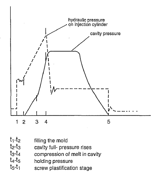
- As the screw moves forward, a nonreturn or check valve in the screw tip prevents backflow of melt into the barrel (Fig. below).
Before injection, the check valve is kept open by melt pressure generated by the rotating screw so that that melt can move through it to the front of the screw.
When the screw nears the end of its forward injection stroke, a limit control is activated to stop it and leave a small cushion of melt, at least 3-mm long, in front of the screw.
The melt volume in the cushion is needed to transmit fluid pressure to the mold during the holding or packing phase that follows the completion of injection.
The cushion also prevents impact at the end of the injection stroke.
Because the pressure in the cushion is an unreliable guide to the pressure in the mold, in most modern machines, control of holding or packing pressure switches over to a pressure transducer in one of the mold cavities when the programmable cutoff point is reached.
In many older machines, reduction to holding pressure is set by an electric timer. In these timer-controlled machines, the injection step is known as stage 1 and holding as stage 2.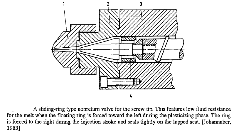
- During the initial part of injection, the melt flows into an empty mold, spreads out elastically, and the hardening melt front forces air out of the cavities through air vents machined in the parting surface and/or through clearances in the ejection pins.
Pressure in the cavities builds up only after they are filled with melt. At this point, injection cylinder pressure should be reduced to the desired holding pressure.
- High pressure is maintained on the cavities during an adjustable holding or packing phase. The pressure during this short but crucial time also may be programmable in up to 10 steps.
During this time, the melt cools and solidifies, crystallization begins, and the part is compressed by the holding pressure to ensure that the cavities are completely filled, and that part density is as specified.
Unless pressure is maintained on the melt as it cools, it will shrink away from the mold surfaces (as it cools, its density increases), or it will not have the minimum cooled density required for high strength.
For Noryl SE100, the recommended holding pressure is 50-80 MPa, preferably measured in the critical area in the cavity where pressure is at a maximum.
The time needed for this phase depends on the shape of the parts being molded, melt temperature, and mold temperature.
If the nozzle does not have a nonreturn feature, holding pressure will prevent the backflow of compressed plastic from the mold to the barrel until the sprue cools sufficiently to seal.
- Mold temperature is controlled by circulation of liquid coolant, either soft water or water/ethylene-glycol mixture, which is arranged to flow turbulently through drilled channels in the mold cavity and core plates.
An external auxiliary heat exchanger chills or heats the liquid, as required. The liquid circulates in various series or parallel-connected paths in the mold and then through the exchanger.
For Noryl SEIOO, mold temperature is set between 65 °C and 85 °C,, which is. About 165 °C -182 °C below melt temperature.
For comparison, its heat deflection temperature at 1.82 MPa is 100 °C, and its flexural strength at 93 °C is about 21 MPa.
Therefore, parts can be safely ejected when they are somewhat above 100 °C, depending on part design. The smallest parts of the flow channels are normally the gates at each cavity.
These gates freeze first, sealing off the cavities.
Holding pressure can be decreased to zero as soon as the gates are sealed and screw rotation restarted to get material melted for the next cycle as soon as the sprue freezes.
Some machines have a sprue break feature; if selected, this feature retracts the pull-in cylinder, and the whole injection unit moves back about 6 mm just after the holding pressure is released, thereby breaking off the sprue.
The nozzle is reseated before the screw is restarted.
- The parts are allowed to cool enough to be ejected without distortion. The core or moving half of the mold is provided with undercuts or other means to ensure that the parts stick in the core half when the mold opens.
Parts naturally shrink onto male core surfaces and away from female cavity surfaces on the stationary half. A timer initiates the ejection phase by stopping the screw and then opening the mold.
If there are side core mechanisms, these are withdrawn first.
Then, a separate ejection or knockout mechanism removes parts that have shrunk onto the mold’s cores. The parts may fall into a simple cardboard carton, takeaway belts or be removed manually or picked up by a robotic arm mechanism or sprue picker.
As in the other steps, mold opening speed may be initially slow to release the parts without damage from the stationary half of the mold, followed by a fast motion and a gradual slowdown at the end of the stroke.
The force and speed applied to the ejection system are also hydraulically controllable. Some machines can be arranged to stroke the ejection plates two or more times to ensure release from the cores and the ejection pins.
- The mold can now be closed. The screw has previously prepared melt for the next cycle, so the injection phase can be initiated as soon as the mold is locked. If something hangs up and prevents closure of the mold, some machines have a try again feature that automatically retracts and recloses the mold once; usually, this permits runners or sprues that have been caught to fall free.
The longest part of the molding cycle is frequently the cooling time for the parts. This depends on the temperature settings, the part wall thickness, and the shape of the part. Assuming a cooling time of 15 s, the overall cycle time for this example can be added up.
- Mold close and lock 2.00
- Injection 3.00
- Screw dwell (hold until gate seals) 2.oo
- Part cooling 15.00
- Mold opening 3.oo
- Ejection and mold opening dwell 3.oo
- Total, s 28.00
- Cycles/hr 128.99
- Cycles/24 hx 3085.00
These figures represent average applications and are given to show the breakdown of the cycle and relative time values. In this example, screw recovery time is 11 s, which is less than injection molding part cooling time, and therefore does not affect the cycle rate.
