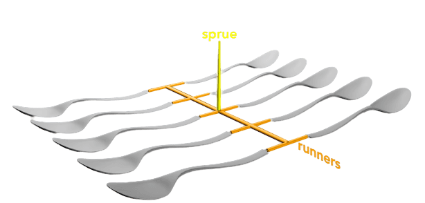
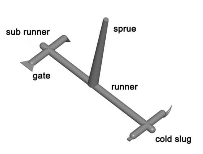
The gate is a short groove with a small cross-sectional area to connect the runner and the cavity. Therefore, the cross-sectional area should be small to obtain :
- Soon after the cavity is injected full, the gate will be solidified
- Simple demoulding
- The part ejection is completed, leaving only a few traces
- It makes the filling of multiple cavities easier to control
- Reduce excessive runner scrap
Gate location and size
1) Place the gate at the thickest part of the product, and injection on the thickest part can provide better filling and pressure holding. If the holding pressure is insufficient, the thinner area will solidify faster than the thicker area. Avoid placing the gate at a sudden thickness change section to avoid hysteresis or short shots.
2) If possible, set the gate in the center of the product. Placing the gate in the center of the product can provide equal length flow. The flow length will affect the required injection pressure. The central gate makes the packing pressure uniform in all directions, also can avoid uneven volume shrinkage.
3) When the melt flows into the runner, the flowing front is the first section to reduce heat (cooling) and solidify when it approaches the mold surface. When the plastic flows forward, the molten material only flows through the solidified plastic layer. And because the plastic raw material is a low heat transfer material, the solid plastic forms an insulating layer but still keeps the plastic flowing inside.
Therefore, the ideal gate should be set at the position of the cross-runner layer to achieve the best plastic flow. This is most common in circular and hexagonal cross-flow channels. However, the trapezoidal cross runner cannot achieve this because the gate cannot be set in the middle of the runner.
When determining the gate location and variety, the following should be adhered to:
- The melted plastic via gates to each cavity should be as even as possible;
- The plastic material injected into the mold cavity should maintain uniform and stable flow fronts at all stages of the injection process;
- The possibility of weld marks, bubbles, cavities, vacant positions, short shot and jetting should be considered;
- The removal of the gate scrap should be made as easy as possible, preferably automatic operation;
- The location of the gate should match all aspects.
There are no fast rules for the method of gate design, mostly based on experience, but there are two basic factors that must be considered:
The larger the cross-sectional area of the gate: the shorter the length of the gate is, the better it is to reduce the pressure loss when the plastic passes through.
The gate must be narrow so that it is easy to freeze and prevent excessive plastic from flowing back. Therefore, the gate is in the runner’s center, and its cross-section should be as circular as possible. The gate solidified time is usually determined by the size of the gate.
The cross-sectional area and gate length can determine the gate size. The following factors can determine:
- Plastic material characteristics
- The thickness of the plastic part
- The amount of material injected into the cavity
- Melting temperature
- Mold temperature
[divider_top]
The gate position guidelines:
- The gate is set in the thick section of plastic parts so that the melt flows into the thin section from the thick section to ensure full-filling;
- The gate position should ensure the plastic filling shortest distance to reduce the pressure loss;
- The gate position should be designed to vent the air in the cavity;
- The gate should not make the melt rush into the cavity. Otherwise, it will leave traces of jetting on the plastic parts, especially for the narrow gate;
- The gate location setting should prevent welding lines on the plastic surface, especially in circular or cylindrical plastic parts, which should set a cold slug at the melting point where 2 fronts meet;
- The gate position for an injection mold with a slender core should be far away from the core so as not to bend the core due to the high-pressure material flow;
- When for large or flat plastic parts injection molding, multi-gates can be used to prevent warping, deformation and short-short;
- The gate should be set in a position that does not affect the appearance of plastic parts, such as the bottom of the edge;
- The size of the gate depends on the size and geometry of the plastic part and the performance;
- When designing injection molds with multiple cavities, the balance of filling should be considered in combination with the balance of runners to fill molten materials evenly at the same time.


