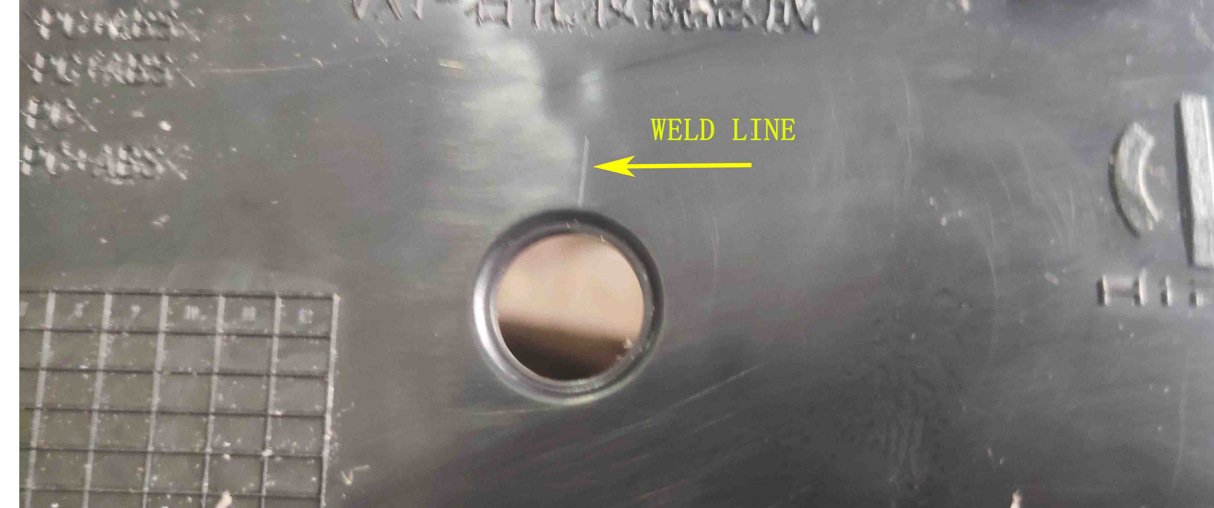
The most common and one of the most challenging injection molding defects are weld and knit lines. Bubbles are caused by melting flow fronts colliding in a mold cavity. In spite of its cosmetic attributes, a bad knit line can significantly compromise a part’s structural integrity. Depending on a number of factors, the strength of an individual knit line can be as low as 25% or as high as 100%.
The choice of material, design, and tooling has an impact on the quality of weld lines. A weld line’s “forgiveness” is dependent on the material. Due to the shear rate and flow rate of the melt front, the shape and thickness of the parts influence the melting process.
Many tooling effects can disrupt and split melt flow into multiple fronts, including gates, bosses, ribs, holes, and depressions in the mold. Also, two parts of the mold surface may have different temperatures.
-
Chains
The knitting of melt fronts can be affected by material characteristics. The strength of the polymer chain is compromised when only partial entanglement occurs. An amorphous resin typically provides a stronger weld line than a semicrystalline resin, and a resin that has a higher flow rate may provide better packing. The addition of glass fibers also reduces the strength of the weld lines.
Resin volatiles can sometimes damage weld lines during processing. The gas can prevent the flow fronts from separating unless properly vented.
-
Weld Lines Due to Design
To determine how well the weld-line holds up, the overall plastic flow pattern during entry into a mold cavity is most critical. Optimizing the efficiency of parts requires minimizing interruptions of the flow, and carefully placing them so they meet and merge at a distance, in order to seamlessly merge.
First, you should place the gate where you do not anticipate that high-stress points will occur during use. The gate locations should be changed to avoid stress in the weld line. You can block some gates on the part if there are multiple gates (but please get permission first!). You can also add an overflow tab to encourage molecular chain entanglement and air venting.
By choosing a gate location that allows for flow and merging after recombined flow fronts, you can enhance welding lines.
In addition, the design of the parts must ensure that the nominal wall is consistent throughout the filling process. If you use resin, you must know how it shrinks and what type you are using. The maximum nominal wall variation for semi-crystalline or high-shrink resins is 17%, while amorphous and low-shrink resins may display wall thickness variations of up to 27%.
The performance of welding lines can be increased if an appropriate gate location is selected once the flow fronts reconverge, causing the polymer to flow and merge along the welding line. A properly vented weld line is also crucial.
The addition of a flow tab may serve as a vent for trapped air as the fronts meet, as well as aid in the better bonding of the fronts.
The flow tab must be cut off in a secondary operation. When designing bosses, ribs, etc., they should be oriented toward the direction of flow. Other options for reducing or removing trapped air include using porous steel inserts or vented core pins. Vacuum venting is another option.
If the tool seems to have a hot spot, let it sit until the temperature is uniform. Compared with the original shot, consider subsequent ones. In the case of a different flow path, temperature or cooling may be at play. Check for hot spots on the mold and make sure it has been uniformly cooled. In both mold halves, the temperature must be the same.
-
Processing
The weld line’s strength and appearance can be improved during welding, but material properties or design faults can not be removed. Molecular chains do not entangle due to a low flow front pressure, causing them to be weak against impact. Occasionally, the weld line may not feel much pressure if the part hasn’t completely packed out.
The presence of trapped air (or volatiles) can make converging flow fronts difficult to knit. Special mold features, such as “blind” holes and core pins, can trap air. In addition, jetting can lead to nonuniform melt flow and poor melding between flow fronts.
Enhancing the injection velocity, decreasing the fill time, and increasing the shear rate often helps.
Cold flow fronts are not always to blame. Chains crossing the flow front and entering the convergent flow have little effect on the temperature of the flow front. The increased volatiles that come off polymers can decrease weld-line strength, especially when the melt temperature is raised to improve flow and weld line strength. This tactic should be reserved for last resort.
As a result, injection velocity can be increased, fill time reduced, and shear rate increased. By doing so, the viscosity of the polymer can be reduced during fill, properly aligning the chain and improving packing. Increasing pack or hold pressure also helps, as well as having longer pack and hold times.
Low-pressure conditions at the weld line can be eliminated by increasing pack or hold pressure. The mold temperature can be boosted by 12° C to promote more entanglement at the weld line.
As much as possible, molders should ensure the weld line gets formed during the first stage of filling. When minimum flow is occurring, it is much harder to get flow fronts to meld together, which makes creating strong weld lines difficult.
By providing flow-leaders to thin areas to fill the thin areas that show an uneven flow front, you may be able to solve the problem of non-uniform flow fronts due to non-uniform wall thickness. The melt pressure for filling is far lower for thicker sections because the part fills preferentially.
A thicker section of the plastic will flow more rapidly, whereas a thin section will stall. As a result, the polymer can “racetrack” around the outer or inner perimeter of a part, allowing trapped gases and air to escape. Increased injection rates and rounding the edge or reducing the thickness of the junction may be solutions. Ideally, the part should be redesigned so that its thickness is uniform.
Flow lines can appear even without an interruption in the flow front, due to the shear-sensitive nature of TPE materials. It is an aesthetic defect even though these flow lines are not true weld lines. Any time the velocity changes, which is what happens as the flow front spreads, these materials can show a flow line.
Try valve gates rather than hot tips to achieve a single melt front on a multigated part and sequence valve gate actuation cascadingly.
