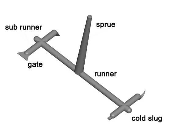
No matter what type of runner system you’re using, there are some basic rules to keep in mind. Unfortunately, some of these requirements may conflict with each other, so you’ll need to find the best compromise.

Rule 1: Decline of pressure
The pressure drop is the difference in pressure between the machine nozzle and the cavity space. This affects the length of the runners, the cross sections of the runners, and the size of the gates. The longer the runners, the smaller the cross sections, and the smaller the gates are, the higher the pressure drop will be. This means that less pressure is available to fill the cavities. The time it takes to cool the runners in a cold runner system will increase because the runners are now larger.
Rule 2: Plastic inventory
In order to avoid degrading the plastic within the runner system, it is important to have as small a volume of plastic as possible in the system between the machine nozzle and the cavity. This is because the larger the runners (less pressure drop), the greater the inventory of plastic will be, and the longer the plastic will be exposed to the heat in the hot runner manifold.
It is better to have less than three times the amount of plastic in the machine than what is needed for one product. This is because the plastic will be replaced more often and will not be exposed to heat for as long. This is especially important for products that take a long time to make or for very small products.
Rule 3: Loss of heat
It’s important to keep the machine nozzle and cavity from losing too much heat. If heat is lost, it can make the plastic harder to inject.
Rule 4: Run with Cold runners
It’s important to keep the area around the sprue and runners cool, so that the molding process can happen quickly. If the runners aren’t cooled properly, it will take longer to finish the molding process.
Rule 5: Run with Hot runner molds
In order to minimize heat transfer between the hot runner and the surrounding plates, the runner system must be well insulated. Due to its location within the mold, and the backing plate used to support it against injection pressure, some heat losses are unavoidable. Contact between these areas of cooled plates and the hot runner conducts heat away from it.
The hot runner manifold heaters are used to compensate for heat losses, increasing the amount of electricity consumed. The heat loss into the surrounding plates can also raise their temperature and impact mold alignment. It is therefore crucial that proper cooling is provided to the surrounding plates.
Rule 6: Balanced runner
There should be no difference in pressure drop between the machine nozzle and each cavity space (gate) in any runner system. In addition, different pressure levels from one cavity to another will affect how much plastic enters the gate before it freezes, how dense the plastic is inside the cavity, and how strong and quality the molded piece is. As a result, the product will also have a different surface definition and appearance. Despite the fact that following rule 6 is not always possible, every effort should be made to do so. A more uniform product may be obtained by adjusting gate sizes individually.
Rule 7: Gates number.
Whenever possible, only one gate should be present per cavity. The following exceptions may be made to this rule: (1) In cases where core shift is a major concern, two or more gates can be placed symmetrically around delicate cores in order to balance pressure and flow around them; (2) in cases where there is a significant flow distance L between the gate and the farthest corner (or rim) of the molding. Moldings with large dimensions are especially susceptible to this.
Rule 8: gates location
A product’s shape determines where the gate should be placed. The gate should be spaced about the same distance from the furthest corners of the cavity space as the gate. If possible, gating at the center of the product would fulfill this requirement, but it is often more expensive than gating at the edge. Occasionally, center gating is not acceptable when the center of the product must be clear or a vestige is not permitted.
Rule 9: plastics flow
As soon as the stream of water from the gate enters the cavity space, it should be broken up by colliding either with an opposing wall or with some projection within the cavity (such as a pin). Flow lines of the plastic, or other surface defects, will not appear as a result of jetting.
Rule 10: Steer clear of backward flow
In some thin areas of the cavity space, plastic may flow easily and quickly around ribs or other heavy sections. As a result, additional fronts are created flowing towards the gate’s front; they trap air, which has to be vented. Ejector pins or vent pins can be judiciously placed in such locations where plastic fronts are expected to meet in heavier moldings, thus providing venting.
