The design process can be simplified by following a three stage approach where material, design and fabrication decisions are made in parallel. SABIC Innovative Plastics engineers should be consulted during the early stages of the design process. Additional information on each of the above steps can be found in the LNP Speciality Compound Design Guide. The following guidelines are reminders of good design practice aimed at producing quality injection molded parts.
Preliminary stage
Define requirements
The design process of a plastic injection molding starts with the understanding of requirements and goals. This can help to determine the selection of materials that are to be used, as well as the best manufacturing method to be utilized.
This includes the selection and specification of raw material such as plastics, metals, wood and others. The raw materials must be compatible with the manufacturing process that is chosen to ensure optimum performance in relation to the end product.
Automation is a key factor in cost reduction for most industries and injection molding is no exception. Therefore it is important to identify methods of production that will allow for greater efficiencies throughout the production process from start to finish.
The variables involved in an injection molding design can be broken down into two groups: The part characteristics and the tooling characteristics. The part characteristics include geometry, wall thickness, surface finish, draft, parting line locations and other features required to produce a high quality finished product. Whereas tooling characteristics include size and complexity (number of cavities), cooling type (air cooled or water cooled), parting line location on tooling, draft angle on parts and gate location on parts. These factors will ultimately determine the minimum volume of parts needed to keep costs low while ensuring delivery dates are met.
Establish conceptual geometry
For injection molding to be successful, conceptual geometry must be established. Conceptual geometry describes the structure of an object in relation to its shape, texture, and size. We must consider how to create the framework that will allow us to manufacture our product in a way that looks as we have intended in order to understand the conceptual geometry of our design. Analyzing the conceptual geometry of our design can be done in several ways.
Observing the physical characteristics of product and determining what makes it visually pleasing is the first step to creating a model of product. The physical characteristics can be converted into mathematical equations to represent the product.
It may also be possible to get insights into how to structure manufacturing process to achieve similar visual results by examining the manufacturing processes from previous products similar to ours.
We could use 3D printing at this stage to build prototypes of different designs and test them out then to find a form that is functional and aesthetically pleasing.
Select materials
Selecting the right plastic material is a critical part of injection molding design. A small mistake in material selection can lead to your customers receiving a faulty product or you losing money on returns. Plastic materials are divided into two groups: engineering plastics and commodity plastics.
Engineering plastics and commodity plastics are two distinct types of plastic that share many properties. Engineering plastics are polymers that have been developed and manufactured with a specific finction, such as being stronger than steel but lightweight. These plastics are created to be used in a variety of applications such as in cars, aerospace equipment, and sporting equipment.
Engineering plastics
Engineering plastics generally have heat resistance and strength higher than that of commodity plastics.
The most commonly used engineering plastic is ABS, which has good impact strength, excellent surface finish, and superior impact resistance (highest of all engineering plastics). It is widely used in automobile parts and appliances.
Polycarbonate (PC) has excellent gloss, transparency, and chemical stability, as well as good impact strength. PC is ideal for transparent housings and covers for electronic devices such as CD players and mobile phones. Engineering plastics are generally more expensive than commodity plastics.
commodity plastics
On the other hand, commodity plastics are polymers created for a wide array of uses and do not have a particular purpose. These polymers include things like high density polyethylene (HDPE) which is found in milk jugs and detergent bottles, low density polyethylene (LDPE) which is used for trash bags and reusable grocery bags, polyvinyl chloride (PVC) which is found in paint and plumbing pipes, or polypropylene (PP) which is used for food storage containers.
The difference in price mainly comes from their properties; the raw materials required to manufacture commodity plastics can be bought at lower prices than those required to make engineering plastics.
Select fabrication method
When designing a plastic product , the first question is whether you have the means to have it manufactured professionally or if you’ll have to do it yourself. Manufacturing plastic parts by yourself is a great way to save money, but it is an extremely complicated process and may take longer than anticipated. You’ll also need a lot of space and equipment, which many people are not able to afford or store.
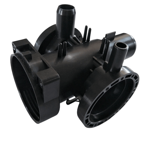
injection
The most common method of professional plastic molding is called injection molding. It’s a process in which molten plastic is pushed into an aluminum mold through a hole called the “gate” by a machine called an “injection press.” Once the plastic has cooled and hardened, the mold can be removed from the part. Molds for more complex parts need to be split into sections with interlocking tabs so that they can be assembled easily.
Extrusion
Extrusion is another popular technique for making parts out of sheet stock plastic. In this process, molten plastic is pushed through a long die (an aluminum cylinder) with many small holes in it. The shape of the resulting pieces depends on the shape of the die and the thickness of the sheets fed into the extruder (the machine responsible for pushing molten plastic through the die). This method is used to make plastic pipes and rods, as well as other long, thin shapes.
blow
blow molding is another common way to make plastic parts. Blow molding is used to produce items such as bottles, buckets, and other round containers. In this process, a pre-made hollow tube is placed over a form (a metal tool that looks like an ice cream cone), which creates a cavity in the center of the tube. The tube is filled with molten plastic and allowed to cool before being removed from the form.
compressing
compressing molding is another common method of plastic production. This process uses a mold to compress molten plastic into a desired shape, such as a bowl or cup. The advantage of this method is that it can be used to create hollow objects with very thin walls.
roto
rotation molding is another common plastic production method. This process uses a mold to spin molten plastic around a core. The rotation causes the plastic to become thinner and longer, which allows it to be molded into one continuous piece of material with no seams or gaps.
CNC machining
CNC machining is another common plastic production method. This process uses a computer-controlled cutting tool to remove material from a solid block of plastic, allowing for the creation of intricate shapes.
3D printing
3D printing is another common plastic production method. This process uses a computer-controlled printer to create objects from small layers of molten plastic that are stacked on top of each other. The plastic is formed layer by layer until the object is complete.
Perform feasibility analysis
The design process is always, inherently, a series of decisions about what to remove. What is the most efficient way to achieve the goal? Which elements are extraneous to that end?
One of the most important questions we ask ourselves during this process is whether the feature we are considering will work in practice, or not. This question is sometimes referred to as “feasibility analysis,” and it’s an important part of designing, because we don’t want to invest all that effort into creating something that doesn’t meet our goal. In this case, I am referring to the current plastic design. There are several different components to this project:
Engineering stage
Complete detailed part design
The engineering stage is the second one in the design process. This step includes complete details of the part design. The primary purpose of this stage is to make sure that an idea has been completely translated into a tangible form.
Here is a summary table for injection molding design considerations:
| Design Aspect | Considerations |
|---|---|
| Wall Thickness | – In order to ensure an appropriate pressure and flow balance during manufacturing, does your design meet or exceed the nominal wall thickness requirements? With a consistent wall thickness in the design, will your part cool evenly? |
| Draft Angles | – What is your draft angle in relation to the shrinkage that you anticipate during cooling?Can your part be ejected from the mold quickly and easily with the planned draft angles? Are you going to overstress your mold with your current design? |
| Corners | – Have the corners been appropriately radiated to avoid shrinkage, warping, shearing, and/or breakage?How well are all corners shaped during molding so that enough material can flow in and a consistent thickness of the wall is maintained? |
| Undercuts | – Is it possible to remove any undercuts from the mold design without altering the intended function of the part?Can the mold be designed to accommodate any necessary undercuts without exceeding the project’s budget? |
| Resin Selection | – Does the part design allow for a proper flow of resin during injection, and will it withstand the required pressure? What factors could affect the part’s cooling time, finish or other properties? How might they be resolved with changes to the design of the part and/or choice of resin? |
| Tolerances | – How do your part’s tolerances affect the tooling process (i.e., changing material selection for a mold, necessitating additional quality checks or creating more complex molds)? In what ways might redesigning the part/mold address performance requirements? |
All the parts are designed and all the dimensions are provided during this stage. This information assists in the manufacturing of a part and the design engineers use it for further development of the product into an actual physical form.
This can help to avoid unnecessary changes and mistakes during the later stages because these errors can be quite costly and may require additional time to fix them. So, by taking care of them at this stage, it is possible to save money and time as well as avoid issues with quality control and delivery of a final product.
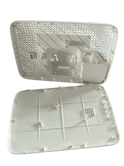
Prototype testing
The Engineering stage is the first time the design is brought to life on a physical level. Testing out the engineering stage can be done with a prototype, which is a rough version of the design meant to represent its overall look. A prototype is built with materials that are much cheaper than those used once production starts and can be used to test out different aspects of the design. Different types of prototypes include:
- Construction mockups: These are made out of cheap materials and are usually only one piece. They are meant to test size, weight, and other physical aspects of the design.
- Visual mockups: These use digital tools to create a representation of the design in CAD software, which allows for easy experimenting with different features without having to create new models every time you want to try something new.
- Functional mockups: These are made out of cheap, easily replaceable materials (such as foam core or cardboard) that can be used for testing functionality. The most common type of functional prototype is a paper model or mockup that uses full-scale images from CAD software or from a 3d printer .
- Design validation prototypes: These prototypes test how users will interact with the final product by testing it out in public and asking for user feedback.
Evaluation and redesign
The goal of the Engineering stage is to create an initial sense of what a finished product might look like, with a prototype that is functional and can be tested. The process of prototyping is iterative; it involves going through multiple cycles of evaluation and redesign. These cycles are what make up the Engineering stage and are the focus of this section.
The evaluation cycle begins with a prototype that has been created in order to test it for its intended purpose, at which point its strengths and weaknesses are identified. Based on this assessment, there may be several possible alterations to improve upon the prototype so that it can better fulfill its intended purpose when tested again. If necessary, new prototypes are created for these iterations, until a version is finally created that fulfills its purpose successfully after being tested.
In the redesign cycle, each iteration of the prototype needs to be evaluated in order to determine if any changes should be made. This time around, however, there will likely not be as many iterations before a satisfactory prototype is created. The goal of each iteration in this cycle is to optimize the design towards fulfilling its intended purpose while using less material, energy, and time than the previous iteration.
Manufacturing stage
Design, build and evaluate a tool
- Quantity: The demands of a production environment can affect the choice of metal used to construct your mold, as well as how that mold is designed.A company with a high planned production volume will benefit from adding more cavities to its molds—producing additional parts per cycle.Because they are more expensive than single cavity molds, multi-cavity molds may not be worth the additional costs at smaller volumes.
- Gates : The way resin flows into your mold and the speed at which it does so can affect whether or not a project is a success. Gates are an important part of designing an injection mold and should be chosen with care to ensure they don’t affect the functionality while making sure they look good.
- Runner: runners are the channels that run from the gates to each cavity and they help to transfer the resin into each part. They can be designed in a number of ways(cold runner and hot runner); some molds might have one direct runner that runs through all cavities, while others may have sub runners for each cavity.
- Parting Line: Because an injection mold is made up of two or more moving halves(core and cavity plate) that fit together, there often has a visible line where the core and cavity plate come together.A skilled mold designer can place parting lines in strategic places to avoid functional or aesthetic problems.
- Cooling: Cooling is an important part of the injection molding process. It allows the plastic to solidify and prevents defects like warpage or bubbles from forming. A well-designed cooling system has many small hoses that circulate cool water throughout the injection mold, preventing overheating , sinks, warping and other drawbacks.
- Venting: venting is a process that allows air and gas to escape from the mold as plastic flows into it. This is important because if there is no venting, then the part will be filled with bubbles that can cause defects. Venting also helps to prevent pressure buildup inside the mold due to trapped gas that can cause warping or other issues.
- Shrinkage: Injection-molded plastic parts will naturally shrink as they cool, with a typical range of 0.4 – 2%. The actual amount of shrinkage depends on several factors: material choice, location and size (dimensions) of the mold gates ,mold temperature,injection and holding presssure, cooling time,etc.The mold must be designed in such a way that it takes shrinkage into account for the part to come out right.
- Over mold:It may be more cost-effective and efficient to design a mold for multi-shot injection if your part needs two or more colors and materials.(the mold is filled with two or more materials simultaneously.) and/or overmolding (where an additional material, such as foam or rubber, is attached to a layer that has already been cooled
Cavity filling analysis
Cavity filling analysis of injection mold design is the most important part of the injection molding process. The cavity filling analysis can effectively improve the quality and productivity of products.
Moldflow is a software used by many companies to perform cavity filling analysis. With Moldflow, you can simulate your product and simulate how it will look after injection molding. You can also study how your product will be processed in each step of the production process. This includes what happens before the material enters the cavity, during injection and after ejection.
Cavity filling analysis is also known as part cycle simulation or PCS (part cycle simulation). It is an evaluation that tests whether a part can be made without any defects during production. The main purpose of this test is to determine if there are any design problems that need to be fixed before further development takes place:
2 of Common injection molding drawbacks due to cavity filling:
flash is a thin band of material around the edge of the part, caused by molten plastic flowing out of the mold cavity and onto the sprue or runner system.
Short shots occur when the molten plastic does not completely fill up the cavity. This is one of the most common injection molding problems and occurs when there is an obstruction or inconsistent flow that prevents complete filling of the cavity. Short shots are most often caused by insufficient cavity filling or incorrect settings on your injection molding machine .
Manufacturing equipment selection
The selection of manufacturing equipment depends on the type of product, its size and design complexity. There are 2 types of equipment used in injection molding: vertical and horizontal. The most common are horizontal machines.
horizontal injection molding
It is common practice to use horizontal injection molding for injection molding – but that does not imply that it is better. Molds are opened and closed horizontally in horizontal injection molding. It is important to maintain consistent, correct injection pressure when filling and cooling mold cavities because of this configuration. A horizontal mold can produce more components per cycle because it typically has more cavities than a vertical mold.These molds, in addition to being horizontally separated, also allow parts to fall out of the cavity upon ejection, without the need for manual extraction.
vertical injection molding
Injection molding machines that operate vertically, such as vertical machines, function similarly to horizontal machines, but they are oriented to operate vertically. Hydraulic, electric, and hybrid executions are available for this type of machine in order to meet the needs of various customers. Injection molding machines orient themselves vertically, which means they require very little floor space . Vertical injection molding machines are particularly suited for insert molding applications. Gravity is used to hold the components in place before overmolding. Injection molding machines often have shuttles or rotary tables that allow loading and demolding within the machine’s cycle time .
Part testing
Part testing is the most important step in the manufacturing process. It is used to ensure that the product meets all requirements. Injection molding is a very complex process that requires careful planning and execution. The quality of parts produced depends heavily on the quality of raw materials and the equipment used.
The following tests are used during this stage:
Functional testing – This type of testing is performed to ensure that each component operates as expected and performs its intended function. The purpose of this testing is to determine if a final product will meet customer needs and expectations. Functional testing occurs at multiple stages throughout development and manufacturing. Testing may include a variety of methods, such as thermal cycling (exposure to high temperatures followed by rapid cooling) and various environmental stress tests (freezing or humidity).
Reliability testing – Reliability testing measures the performance of a product over time under specific conditions (such as temperature range or humidity). The goal is to determine how well a product will perform when used over an extended period in real-world applications. Reliability tests are often conducted on products before they reach customers, but they can also be used for aftermarket purposes by checking if certain components continue working properly after being used for several years.
Safety testing – Safety testing involves exposing products that are designed for human use to certain physical or chemical hazards and determining how safe they are. Safety tests may be conducted on toys, vehicles, medications, or other products that could potentially harm someone if they fail.
Customer evaluation
Customer evaluation process is an important part of any business, especially in the manufacturing industry. It is essential that you know what your clients want and what they expect from your company. Customer evaluation process helps identify areas of improvement in your business and helps you deliver better products and services to your customers. Injection molding is one of the most important processes in the manufacturing industry because it allows you to mass produce high quality products at a low cost. However, when making such a large investment, it is important that you have a good understanding of how well your product can be received by the market. This can be done through customer evaluation process.
