The plastic mold can be viewed as an exchanger that carries the heat of the hot melt away from the plastic mold by the circulating refrigerant.
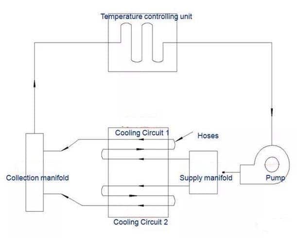
The cooling system plays an important role
- Increase productivity
- Make sure the mold removal process is effective.
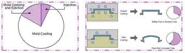
More than two-thirds of the thermoplastic injection molding cycle is devoted to cooling the mold. An efficient cooling system reduces mold cooling time, and therefore increases overall production.
Also, even cooling has the capacity to control the warping of the finished product by eliminating uneven heat transfer. Hence, even cooling has the ability to maintain the accuracy and stability of the size of the product in addition to improving the quality.
Cooling has the following objectives:
- Increased quality of the product due to balanced cooling
- Increased productivity through effective cooling
For example, the following factors can be taken into account when designing the mold cooling system:
- cooling channel size;
- cooling channel position;
- cooling channel type;
- cooling channel configuration and connection;
- cooling channel total length and cooling medium flow rate; The most commonly used cooling hole diameters are: Ø6mm, Ø8mm, Ø10mm, Ø12mm; the specific design dimensions are shown below:
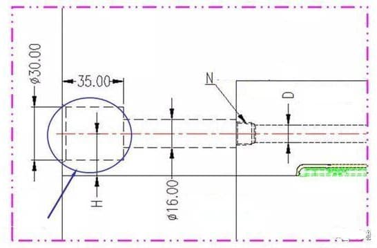
Note:
- (1) When D=Ø6mm, N=PT1/8”;
- (2) When D=Ø8mm, N=PT1/8”;
- (3) When D=Ø10mm, N=PT1/4”;
- (4) When D=Ø12mm, N=PT3/8”;
- (5) When H<=25mm, do not machine quick joint hole
In order to effectively cool the mold and improve the heat transfer efficiency , the design of the cooling channel should be considered carefully;
The cooling channel depth (d) , the distance (P) and the diameter of the channel (D) relationship is as follows:

- d (depth), from D to 3D
- P (distance), from 3D to 5D
The design principle of the channel position:
(1) The design and arrangement of the cooling tunnel should be compatible with the wall thickness of the plastic product; the thicker part of the plastic product should have better cooling.
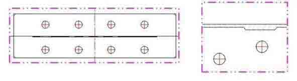
(2) The cooling channel should not be too far or too close to the mold wall ,to avoid affecting the cooling effect and the strength of the mold. As shown below: (H : from 11mm to 13mm)
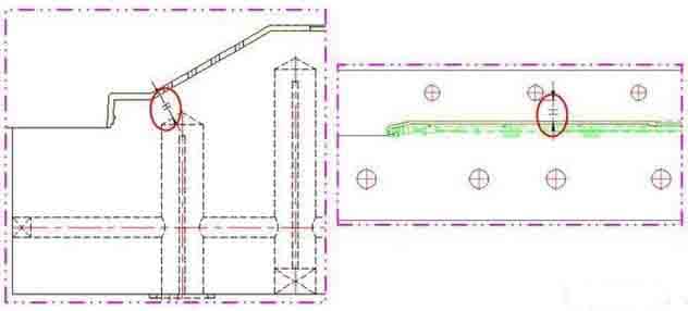
(3) The distance between the cooling channel and the ejector pins, the sleeve, the lifter (P) is 5 mm or more. As shown below: (P value is at least 3 mm)
Cooling channel design
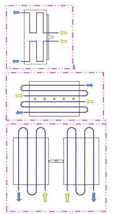
The layout of the cooling channels should be based on the shape of the plastic product and cooling temperature.
- Straight-through
- Circulating
- Baffle
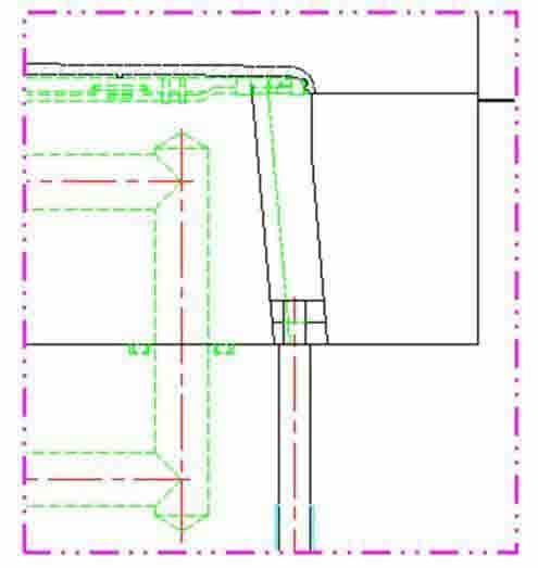
A baffle is typically used on cavities that are a far distance away from the cooling tunnel; the baffle is in fact a cooling tunnel that drills vertically through the main cooling pipeline, and utilizes a baffle to divide the pipe into two Semicircular wires.
The coolant moves in one direction from the cooling tunnel into the baffle, then turns around to the opposite side at the top of the baffle, then returns to the cooling tunnel.
When the finished product is relatively deep, a pipe is cut in the mold, and the cooling water is sprayed from the pipe to flow to the surrounding cooled wall.
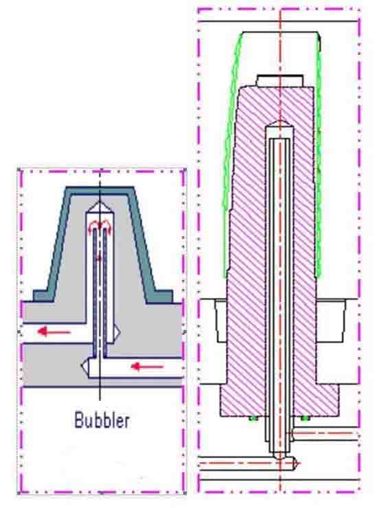
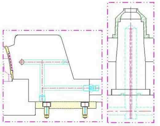
Spring cooling works just like baffle cooling except that a small sleeve replaces the baffle. Coolant flows trough the tube and then flows into a fountain at the top.
The temperature of the elongated mold core is best cooled by spring-type cooling. The outer and inner diameters of the sleeve must be adjusted to give a flow resistance of half between the inner and outer sections: outer diameter and inner diameter of the core.
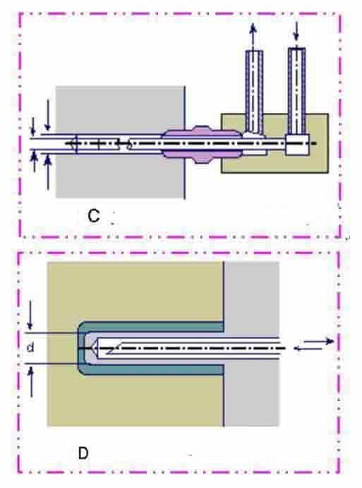
(Figure C) Pipe fittings less than 5 mm in diameter are usually screwed directly into the mold core. (Figure D) In this case, they may need to be beveled on one end to increase the cross-sectional area of the outlet.
In addition to the cooling of the mold core, the spring pipe can also be used in the flat areas where drilling or grinding cannot be carried out.
Special form
When the cooling channel is limited by the finished product or mold structure, it will use the following:
thermal pipe
The spring pipeline and baffle type raise flow resistance mainly due to their narrow flow area. Therefore, the proper dimensions must be measured when designing these devices. The baffles and springs must be documented and analyzed in CAE software.
The thermal pipe is an alternative to baffle type and spring pipeline. In the inner thermal pipe(pin), a closed cylinder filled with fluid absorbs heat from the mold and evaporates, releasing it to the coolant and condensing.
In order to ensure good thermal conductivity, it is important to avoid air bubbles between the thermal pipe (pin) and the mold or fill the air pockets with a sealant with a high thermal conductivity.
In the case of narrow mold cores, air cooling will only be practicable using one opening. The air is blown in through the open center hole of the mold core.
The best way to cool thin cores of less than 5 millimeters is to use a substrate with a high thermal conductivity, such as beryllium copper or copper, as an insert.
Inserts of beryllium copper or copperare inserted into mold cores, one end with a larger cross-section is placed into the cooling tunnel, and the other on the lower end of the insert.
For large mold cores (greater than or equal to 40 mm), the coolant must be delivered to the center of the mold core. A double spiral line can be used to cool the cylinder or the circular part .
In this case, the coolant flows from the top of the mold core through one spiral to the bottom of the mold core through the other spiral. Due to design factors in this case, the walls of the mold core must be thicker than 3 mm.
Turbulence
The waterway responsible for the main cooling task should maintain turbulence.

Cooling tunnel configuration and connection
In the design, we often use O-rings to connect the cooling holes between different accessories. The model and design standards are as follows:
Cooling of the sprue
Enhance cooling near the gate
During the filling process of the plastic melt, the temperature is generally higher near the gate; therefore, the cooling near the gate should be strengthened. For this reason, the cooling water should flow from the vicinity of the gate to other places. (As shown below)
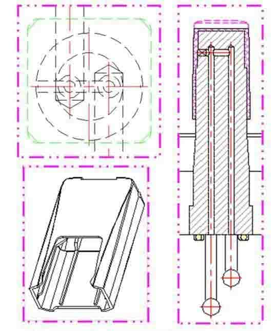
Cooling of the insert and the slider
Due to the insert and slider separating the contact surfaces and creating a gap, the heat conduction will be changed (since the air in between is a poor conductor of heat and thus the heat will be unable to escape).
This is why the cooling system should be incorporated into the slider and the insert to the greatest extent possible.
Plastic injection molding relies heavily on its cooling system. A proper cooling system can greatly reduce production costs and shorten molding times.
| Material | Barrel Temp (°C) | Mold Temp (°C) |
|---|---|---|
| ABS | 210-240 | 60-80 |
| ASA | 180-270 | 55-75 |
| HIPS | 190-260 | 40-70 |
| PC | 280-320 | 80-120 |
| PE | 180-250 | 50-70 |
| PP | 240-280 | 40-60 |
| PVC | 150-200 | 40-50 |
| POM | 210-230 | 60-80 |
| PMMA | 220-270 | 30-40 |
| PA6 | 250-310 | 40-90 |
| PS | 210-240 | 40-90 |
| TPU | 130-180 | 40 |
