If the molding defects are present, plastic automotive components could be subject to rejection, rework, and large increases in production costs. These defects often appear during the end product review, when it may be too late to fix.



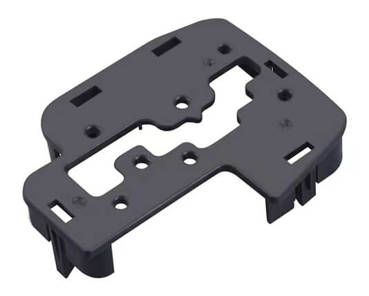
This is why it is important to prevent costly situations. Vehicle safety and reliability can be affected by the quality of automotive components. Product engineers can influence the outcome when they know what to look out for. They can also partner with experienced complex injection molders who can help them prevent or correct common mold defects such as:
Short shotting
Short shot molding is caused by molten plastic not filling the mold cavity properly and leaving some areas without plastic. This inconsistency can quickly lead to a faulty product.
General causes: There are many possibilities, including improper shot calibration or plasticizing capabilities, early solidification of too thick plastic, trapped air due to poor degassing and gas venting, and early solidification.
Solutions: Injection molders look at the problem from the cause angle.
Increasing the injection pressure, speed, and temperature can correct fill rate and hesitation issues.
You can fix flow restrictions by clearing frozen flow channels or using mold redesign.
Mold can add air vents near the ends of affected channels to solve inadequate venting. for more
weld Lines
The flow and weld lines result from how molten plastic moves through a mold. Flow lines show the physical path of plastic before and after cooling. From separate mold parts, weld lines indicate where plastics join together.
General causes: Flowlines are caused by varying molten-plastic flow speeds, directional changes within the mold contours, wall thickness variations, or injection speeds too slow for consistent solidification. When two or more flow fronts fail to bond properly due to partial solidification, weld lines can occur.
Solutions:
Injection molders can optimize flow lines by optimizing injection speeds and pressure, adjusting locations where wall thicknesses or flow directions abruptly change or locating gates within the component’s thinner walls.
Injection molders can raise melting plastic temperatures and increase injection speeds for weld lines. They also rethink the design to create a single source flow.

Burn and sink marks
Burn and sink marks are the result of cratering in thicker components and brown surface discolorations. Sink marks are shrinkage in the inner parts of the component. Burn marks are material degradation.
There are several causes of sink marks: Insufficient cooling and curing can cause sink marks, as well as incorrect cavity pressures or excessive gate temperatures. Burn marks can be caused by too rapid or excessive heating.
Solutions:
Injection molders can lower mold temperatures, increase holding pressure, or adjust holding times to make sink marks. This allows for greater cooling and curing.
Injection molders can reduce injection speeds, mold, and melt temperatures and optimize gas venting and degassing for burn marks.
WARPING
Uneven shrinkage in the mold’s various parts can cause warping.
General causes: The materials are stressed, and cooling is not uniform. When internal stresses are removed, parts can twist, bend, or become otherwise deformed.
Solutions: Injection molders stop warping by:
To minimize residual stresses, monitor and adjust cooling times.
To ensure that molten plastic flows in one direction, design the mold with a single wall thickness.
You should choose plastics that are resistant to shrinking or deformation. This means avoiding semi-crystalline materials.
Product engineers are committed to preventing or fixing defects in automotive applications. They seek out injection molders who have the expertise, knowledge, and attention to detail needed for success in custom or standard injection molding.
| PROBLEM | REASON |
|---|---|
| 1. Short shot | The plastic parts made by plastic injection molding companies have irregular and incomplete edges. It usually occurs at the farthest point of the gate, the roots of thin and long ribs. |
| 2, Shrinkage | Occasionally, a place 1. when the material thickness is uneven, 2. thick section of injection molded part, 3. boss and rib section. Due to shrinkage, the plastic parts develop dent, uneven, and wavy under low light |
| 3, Flash | A part edge with an extra thin layer of plastic is often found in the following locations 1. Parting line; 2. Moving core; 3. Ejector pin position, boss position, hole position, snap location |
| 4. Bubbles | The bubbles on the plastic surface are of a different color from the surrounding colors and are typical 1. bubbles caused by gas, air, and water-gas that are not released in time. 2. bubbles caused by shrinkage. The bubbles in the transparent part are particularly distinct. |
| 5. Weld line | When multiple molten flow fronts coincide with each other, a deep weld mark appears on the surface of a plastic part. This most commonly occurs at the confluence of multiple molten flow fronts. |
| 6, Burning | it is not a flat surface. It is usually dark or black spots; usually, they are found in sections where it is difficult to fill and trap the gas easily. |
| 7, Black spots | black impurities are evident on the surface of the plastic parts, mainly caused by the use of mixed materials. |
| 8. Discoloration | The slight difference in color between the actual plastic part and its required color is very apparent, and it is generally because the pigment is incorrect, the mix ratio is incorrect, or the mold is set at the wrong temperature. |
| 9. Wrinkles | The plastic parts show wavy lines on the surface caused by the cooling of the resin flowing. |
| 10. Deformation | The plastic parts have distortions, undulations, curves, and this is particularly common in the bosses, ribs, and round-shaped injection parts. These are especially common to PP injection molding. |
| 11. Wrong materials | In contrast to the specified materials, the one here can be identified by checking out the packaging label, the density, the burning continuity, the color of the flame, the color of the smoke, and the length of flames. |
| 12. Stick to the mold | Incomplete plastic part staying in the cavity, in contrast to short-shot, or due to the lack of designing the mold ejector system, the plastic part is hard to be ejected from the cavity, generally in thin-walled areas, bosses, and snaps. |
| 13. Scratch | The surface of the plastic parts rub against the surface of the cavity during the ejection so that a lot of them have scratches on the surface. |
| 14, Over-flow | It is caused generally by cavity damage and occurs on the active section, bosses, ejector pins, and parting surface. |
