Runnerless Mold
A runnerless or hot-runner mould system could be considered as an extension of the moulding machine injection unit.
In this case,the polymer is kept molten right up to the cavity gate by means of additional heating elements controlled by thermocouples.
The working temperature of the hot-runner system is not dissimilar to that of the molten polymer being processed.
In order to maintain a stable running temperature, the hot feed system is either insulated from the rest of the mould,e.g. by an air gap,or controlled by the addition of cooling channels within the immediate vicinity.
The choice of method depends on the design of hot feed system adopted.
Advantages of the hot-runner mould
The principal advantages of employing a hot-runner mould are:
- (a) reduced cycle times as a result of having a component cooling requirement only. The runner and feed system remain molten above the quickly frozen gate.
- (b) material savings result from having no sprue or runner systems to granulate or dispose of. Without the subsequent regrind addition to the initially fed material,shot and production consistency is maintained throughout the production run.
- (c) labour and post-moulding finishing costs are significantly reduced without the need for degation of the mouldings.
- (d) the ability to gain greater control over the mould filling and flow characteristics of the molten polymer during the filling phase of the moulding cycle. This can be achieved by locally altering the temperature of the feed system within the vicinity of the subject area.
In the case of the hot-runner mould, the relative advantages usually outweigh its limitations.
Certain limitations such as colour changing and reliability have to be carefully considered when deciding on either a conventional mould or the hot-runner alternative.
In cases where high volumes of mouldings are required at low cost, the hot-runner option often provides the only logical route to take.
Hot-runner systems
Many designs of hot-runner mould exist. They tend to vary according to system design and individual manufacturers.
Rarely are any two manufacturers’ systems compatible with each other,either in size or design of assembly.
Variations exist in terms of the method of heater supply and control, some being AC supplied, others being DC supplied,and requiring their own special heater/controllers and built-in transformer units.
After surveying all the hot-runner mould types and variations, there appear to be three general groups into which they may be categorised.
- Group 1 – Externally heated manifold moulds.
- Group 2 – Internally heated manifold moulds.
- Group 3 – Insulated hot-runner moulds.
In addition to the above groupings, individual mould designers and system manufacturers frequently utilise design features from more than one group. For this reason group 4 has been added.
- Group 4 – Mixtures of the aforementioned.
The externally heated hot manifold mould

The figure above illustrates a typically encountered construction layout of an externally heated manifold hot-runner mould. The design centres about the ‘hot, manifold block (HMB) into which a cross-drilled runner/feed system is machined.
Each runner flow channel is drilled and plugged off accordingly until the required runner layout is achieved.
Care must be taken when designing the runner layout of the manifold block to ensure that flow “dead” or “blind”,spots are not created where degradation of the polymer could occur in use.
Features such as profiled end plugs can be incorporated into the right angled corners of runner intersections to reduce the chance of flow dead spots being created.
Heat is applied to the manifold block by means of cartridge or bar heaters sited in drilled holes about the melt flow channels.
Correct positioning of the heater sites is essential if even thermal saturation of the block is to be achieved.
Thermal control of the block is aided by the location of thermocouples sited in between the heating elements and the flow channels. These are in addition to those already built into the heaters themselves.
In order to maintain a thermal balance between the manifold block and the rest of the mould, an air insulation gap should be incorporated into the mould design.
A gap of approximately 6 mm is normally considered sufficient for general moulding temperatures.
The gap is achieved by sealing washers about the flow channel outlets at the front of the block and support blocks situated at the rear of the block against the mould back plate.
The manifold is usually centred to the rest of the mould by dowel pins located into the front of the block which allow expansive forward movement to occur,but resist lateral movement of the block across the sealing faces of the compression washers.
In order to achieve a good sealing shut-off between the manifold sealing washers and the backs of the cavity gates,a shut-off contact interference loading is required.
The interference loading is generated by the thermal expansion of the manifold block and the BeCu sealing washers which crush under load to form a compression seal against the backs of the gates.
Failure to sufficiently ‘heat soak’ the manifold block prior to use may result in polymer leakage at the seal faces resulting in blown manifold heaters and the need for a costly rewiring of the heaters and thermocouples.
The advantages and disadvantages of the externally heated manifold hot-runner mould may be summarised as below.
-
Advantages:
(a) Good pressure transmission to the cavity gate as a result of almost totally molten polymer flow throughout the heated runner cross-section.
(b) Small section runners reduce material hold-up times within the feed system resulting in less polymer degradation when compared to other hot-runner designs.
(c) Consistent output once thermally settled and running.
-
Disadvantages:
(a) Susceptible to material leakages at sealing washer seats resulting in an additional mould servicing requirement, i.e. replacement of the BeCu sealing washers between runs.
(b) Preheating or ‘soaking,of the manifold block prior to use:Preheating of the manifold usually takes approximately | hour to ensure that a leak free shut-off exists between the block,washers and gates.
(c) Feed control of individual impressions is limited due to the general heating effect of the design. If the feed control needs to be individually adjusted to any singular impression, the gate geometry or bore diameter of the scaling washer is altered to suit.
(d) Less economical to run than other hot-runner designs, in terms of higher electrical heating power input required, in comparison with the processing output of the design.
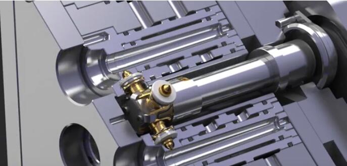
The internally heated manifold mould

Figure 2.
In the case of the internally heated hot-runner mould, molten polymer is routed about the hot-runner or distributor block (Figure 2.) contained within large diameter (32 mm typical) cross-bored flow ways.
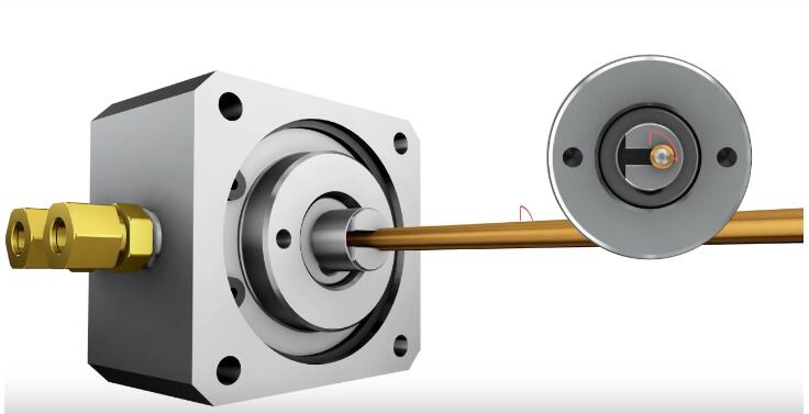
Steel tubes containing cartridge heaters with built-in thermocouples are centrally supported by end caps secured in position at the end of each flow bore and usually anchored by either dowel pins or shoulder bolts.
On entry into the mould, the molten polymer flows about the heated tubes as it flows through the feed system, remaining molten while in contact with the heated tubes and freezing to form a skin within the cooler channel outer walls.
Skin thickness is decided by the temperature of the surrounding hot-runner block (HRB) processing temperature of the molten resin and the hold-up time experienced during cycling.
To achieve a working thermal balance, the temperature of the hot-runner block must be controllable about the distribution tubes. For this purpose drilled cooling channels are incorporated into the block design.
Positioning of the block cooling channels should be such as to remove excess heat from behind the block to the moulding machine platen and to the front of the block,to the mould cavity plate.
Failure to dissipate excess heat from the HRB effectively reduces the size of the processing window available during use. Quality output from the mould will also suffer accordingly.
Filling control of individual cavities is achieved by the incorporation of a heated tipped probe behind each gate. Each probe is individually heated by its own cartridge heater and controlled by an individual thermocouple.
Probe height is determined by altering the thickness of the probe seating washers located under each probe shoulder. By altering the probe height and the heater temperature, the filling of the cavity can be accurately controlled. Even relatively unbalanced feeding layouts can be set to fill evenly using such a system.
The effective height of the probe in use has to be calculated prior to setting the mould up and account has to he made for the thermal expansion of the probe material (usually alloy steel) when at running temperature.
When in use, the probe is subject to natural wear and tip damage and should therefore be considered as a standard mould part with spares held accordingly.
In order to reduce setting and servicing costs, individual probe setting heights and running temperatures should be noted and recorded for later reference and information purposes.
The advantages and disadvantages of the internally heated manifold mould may be summarised as follows.
1. Advantages:
(a) Good filling control to individual cavity gates. The use of individually heated and controlled probes behind each gate enables accurate and balanced filling control to occur across the whole mould once set.
(b) Reduced gating problems. Problems such as gate blockage are reduced as a result of the use of the heated probe set-up.
(c) Good moulding accuracy control available to each moulding.
(d) The ability to individually “blank off” defective impressions which is achieved by turning off the subject probe heater.
2. Disadvantages:
(a) Contamination from the HRB. Blind spots exist at the end of each distributor tube where the polymer stagnates and degrades if not solidified.
(b) Colour contamination of polymer during use, especially if colour changes are to be undertaken. The combination of blind spots and the skinning effect of the polymer inside the flow bores are all sources of possible colour contamination which are more pronounced if higher processing temperatures are encountered later on during mould use.
(c) nozzle tip wear and damage during use. nozzle tips are easily damaged by the gate walls if the nozzle is inadequately supported when in use,most of the damage occurring during the higher pressure first stage of the moulding cycle.
The tips naturally wear in use due to the abrasive action of the pressurized polymer, especially if reinforced or filled in any manner.
(d) Gate blockage. Degraded polymer or foreign matter usually collects between the nozzle tip and the cavity gate wall which eventually results in a blocked gate.
The insulated hot-runner mould
The insulated hot-runner mould is the simplest of all the hot-runner designs. The design relies upon the principle that polymers are good insulation materials with relatively high specific heat capacities.
Molten polymer is initially injected into the flow channels and a skin is formed on the polymer in contact with the cooler channel walls.
The skin serves to effectively insulate the molten core of the feed material as it progresses through the mould to the cavity gates.
Flow channel skin thickness is determined by the temperature of the mould plates, temperature of the polymer flowing through the system and the length of the moulding cycle time.
With this tool design the mould feed block is split onto two plates allowing access to the feed channels once taken apart.
The large diameter (25-35 mm typical) feed channels are half form machined into each plate using a bull-nosed end milling cutter, the full diameter being created on assembly of the two plates.
Stripper plate Core control of the feed plates is essential if the mould is to function consistently while in use; coolant flow channels must be provided in front of and behind the feed channels to obtain control.
Insulation hoarding, i.e. fibre glass plate (typically 6-10 mm thick), should also be added to the mould backing plates to minimize thermal loss to the machine platens.
The advantages and disadvantages of the insulated hot-runner mould may be summarized as below.
Advantages:
(a) The feed system can easily be stripped and cleaned, resulting in very little material or colour contamination occurring. Feed system cleaning or deslugging, is often carried out in the moulding machine. Access to the solidified feed system is obtained by unbolting and latching the frontal plate to the moving half of the mould and opening the press.
(b) Mould start-up times are faster when compared to other hot runner mould systems.
(c) Moulds are very much cheaper to manufacture than the other hot runner mould designs.
(d) Thermally unstable polymers may be processed using such a system.
Disadvantages:
(a) Freezing-off of the feed system. Stoppages during the production run will result in the solidification of the feed system and the need for its removal before production can restart or continue.
(b) Gate blockages may be caused by a frozen ‘plug’ of material caught in the cavity gate left from the previous shot. Gate ‘plugging’ is a serious problem with the insulated hot-runner mould design. To overcome this problem, heated nozzles are often situated behind each gate . The addition of nozzles into this mould design results in a very competent mould being produced but at the cost of significantly increasing the overall tooling expenditure.
(c) High pressure losses within the feed system. The relatively large diameter of the feed channels results in a large pressure drop occurring due to the high compressibility of polymer melts generally .
