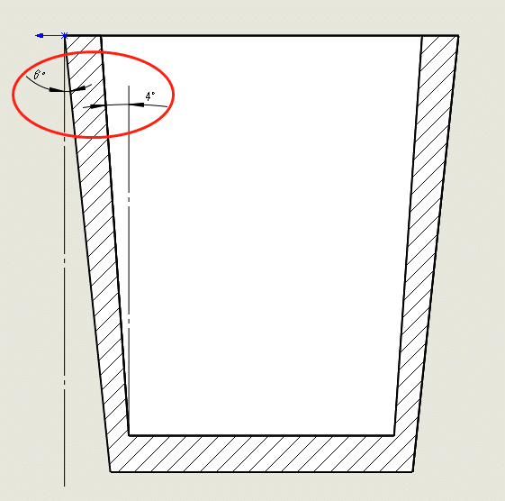
There is no certain criterion for the size of demoulding draft angle, and the most are determined by moldmakers experience and the deep draw of products. In addition, the molding method, wall thickness and plastic material should also be considered.
Generally, a certain amount of demoulding draft angle is required for any side of the molded product so that the product can be smoothly ejected out of the mold. The draft angle is usually 0.5 ~ 1.
Rule of thumb, the following points need to be followed:
If the plastic part requires high dimensional accuracy and small shrinkage, a smaller draft angle should be selected, such as 0.5.
For deep draw and larger injection molded part, mold maker need to take the smaller draft angle according to actual demand.
If the shrinkage is large, a larger draft angle should be selected.
When the plastic part wall thickness is thick, the molding shrinkage will increase, and the demoulding draft angle should be larger.
The demoulding draft angle of transparent parts should be increased to avoid scratching. Generally, the demoulding draft angle of PS materials should be no less than 2.5 ~ 3, and that of ABS and PC materials should be no less than 1.5 ~ 2.
The sidewall of plastic parts with texture, sandblasting, etc., shall have a demoulding draft angle of 2 ~ 5, depending on the specific texture depth.
The deeper the texture depth is, the greater the demoulding draft angle should be.
When the structure is designed to be shut-off, the draft angle of the shut-off surface is generally 1 ~ 3.
The direction of draft angle. Generally, the inner hole is based on the small end, which conforms to the drawing. The draft angle is checked from the large end, the shape is based on the large end.
The demoulding draft angle is not included in the tolerance range of plastic parts as a rule of thumb.
The demoulding draft angle of the shell profile plastic part is greater than or equal to 3. Except for the shell surface, the demoulding draft angle of other features is 1.
In particular, it can also be taken according to the following principles: the demoulding draft angle of reinforcing ribs:
- < 3mm, draft angle is 0.5,
- 3 ~ 5 mm, the draft angle is 1, and
- > 5mm,draft angle is 1.5;
The demoulding draft angle of draw depth:
- <3mm, the draft angle is 0.5,
- 3 ~ 5 mm, draft angle is 1
- >1.5mm, draft angle is 1.5
Wall thickness of plastic parts

It is very important to determine the wall thickness of plastic parts reasonably. The wall thickness first depends on the requirements of plastic parts, including the strength, quality, electrical performance, dimensional stability and assembly requirements. Generally, the wall thickness has fixed values as a rule of thumb, which can be determined by referring to similar ones.
| Engineering plastics | Minimum wall thickness | Wall thickness of small products | Wall thickness of medium products | Wall thickness of large products |
|---|---|---|---|---|
| Nylon (PA) | 0.45 | 0.76 | 1.5 | 2.40~3.20 |
| Polyethylene (PE) | 0.6 | 1.25 | 1.6 | 2.40~3.20 |
| Polystyrene (PS) | 0.75 | 1.25 | 1.6 | 3.20~5.40 |
| Modified polystyrene | 0.75 | 1.25 | 1.6 | 3.2~5.4 |
| Organic glass (PMMA) (372) | 0.8 | 1.5 | 2.2 | 4.00~6.50 |
| Polypropylene (PP) | 0.85 | 1.45 | 1.75 | 2.40~3.20 |
| Polycarbonate (PC) | 0.95 | 1.8 | 2.3 | 3.00~4.50 |
| Polyoxymethylene (POM) | 0.8 | 1.4 | 1.6 | 2.40~3.20 |
| Polysulfone (PSU) | 0.95 | 1.8 | 2.3 | 3.00~4.50 |
| ABS | 0.8 | 1.5 | 2.2 | 2.40~3.20 |
| PC+ABS | 0.75 | 1.5 | 2.2 | 2.40~3.20 |
| Polyvinyl chloride (hard) | 1.15 | 1.6 | 1.8 | 3.2~5.8 |
| Polyvinyl chloride (soft) | 0.85 | 1.25 | 1.5 | 2.4~3.2 |
| polyamide | 0.45 | 0.75 | 1.5 | 2.4~3.2 |
| polyphenyl ether | 1.2 | 1.75 | 2.5 | 3.5~6.4 |
| polysulfone | 0.95 | 1.8 | 2.3 | 3.0~4.5 |
| Chlorinated polyether | 0.9 | 1.35 | 1.8 | 2.5~3.4 |
| cellulose acetate | 0.7 | 1.25 | 1.9 | 3.2~4.8 |
| ethyl cellulose | 0.9 | 1.25 | 1.6 | 2.4~3.2 |
| Acrylic | 0.7 | 0.9 | 2.4 | 3.0~6.0 |
The wall thickness of plastic parts should be uniform as far as possible, avoiding too thin wall, too thick wall, and sudden wall thickness change.
If the wall thickness of plastic parts must be changed, gradual change or circular arc transition should be adopted. Otherwise, the plastic parts will be deformed due to uneven shrinkage, which will affect the strength of plastic parts and the fluidity during injection molding.
Thickness difference shall be controlled within 25% between each wall, and the minimum wall thickness of the part shall not be less than 0.4mm, and the area shall not be greater than 100mm².
The wall thickness of plastic parts is generally in the range of 1 ~ 5 mm. The most common is 2 ~ 3 mm.
Try not to design ribs and boss too thick. It is recommended to take half of the body wall thickness. Otherwise, it will easily cause appearance problems such as sink marks.
Try not to design the part as a single flat plate with a very small size. Otherwise, the deformation will lead to the unevenness of the part.
-
Injection molding hesitation
Hesitation refers to a phenomenon in which one flow is caused to slow down or stop at a specific point in the flow path. The thick passage in a cavity in which the plastic will fill first is more likely to present less resistance to the flow of plastic than a thin passage.
Depending upon where the gate is to be placed, The cavity can either be filled with a thin or thick section by melt plastic. However, the thicker section will usually cover the space first because the flow resistance along the thicker route is less. Consequently, the plastic can start to slow down in the thin section and eventually stop.
If the plastic slows down once it starts to cool, it will lose viscosity more rapidly, so this will inhibit the flow, even more, making the plastic harden. At that point, the problem is self-propagating as the plastic itself begins to have a hardened surface.
Hesitation can develop due to the significant changes in the wall thickness/shape of the flat ribs and the thin section of the parts that have a large deviation in wall thickness/shape.
Whenever a part injection molding is hesitant, it can reduce product quality since there will be variations in surface appearance, poor packing, or high stresses. Changes in the orientation of plastic molecules may change the part’s quality. Another possibility is that the flow front can freeze, leaving the cavity unfilled(a short shot) because of the hesitation.
-
Here’s what you need to do
It is recommended that the injection point is moved away from the region of hesitation so that a bulk fill of the cavity will occur before filling the thin area. Getting rid of these alternative flow routes will help decrease the chance it takes the polymer to hesitate.
It can be done by moving the area where the polymer injection is made to an area with greater pressure applied where the hesitancy occurred. A thin region of the ribs or bosses is the last place to inject to apply all the injection pressure at the same point.
To reduce the resistance to flow, increase the wall thickness at the point where the hesitation occurs.
It is best to use a less viscous substance for injection molding (one with a higher melt flow index).
Inject more swiftly, so the injection can be carried out without hesitation.
The melt temperature should be raised so that it flows more easily into the thin area.
